Drainage wire fixing device

A technology of fixing device and drainage wire, applied in the direction of cable suspension device, etc., can solve the problems of inconvenient operation, time-consuming and labor-intensive, etc., and achieve the effect of convenient and fast fixing

Active Publication Date: 2022-03-01
GUIZHOU POWER GRID CO LTD
View PDF6 Cites 0 Cited by
  • Summary
  • Abstract
  • Description
  • Claims
  • Application Information

AI Technical Summary

Problems solved by technology

[0002] In the power line, when the user needs to take power from the main line for use, it needs to connect the main line to the user terminal through the drain line. Since the main line is at a high place and the user end is at a low place, the drain line is connected from a high place to a low place. To avoid the influence of the gravity of the drain wire itself on the reliability of the terminal connection, or to avoid the large impact of the wind on the drain wire terminal in strong winds, it is necessary to bind the middle part of the drain wire to the insulator with an aluminum wire; In the operating procedures, it is stipulated that several rounds of binding are required to maintain the reliability of the binding; the entire binding process is carried out in mid-air, and the binding round after round is not only inconvenient to operate, but also time-consuming and laborious

Method used


Image

  • Drainage wire fixing device
  • Drainage wire fixing device
  • Drainage wire fixing device

Examples


Embodiment 1

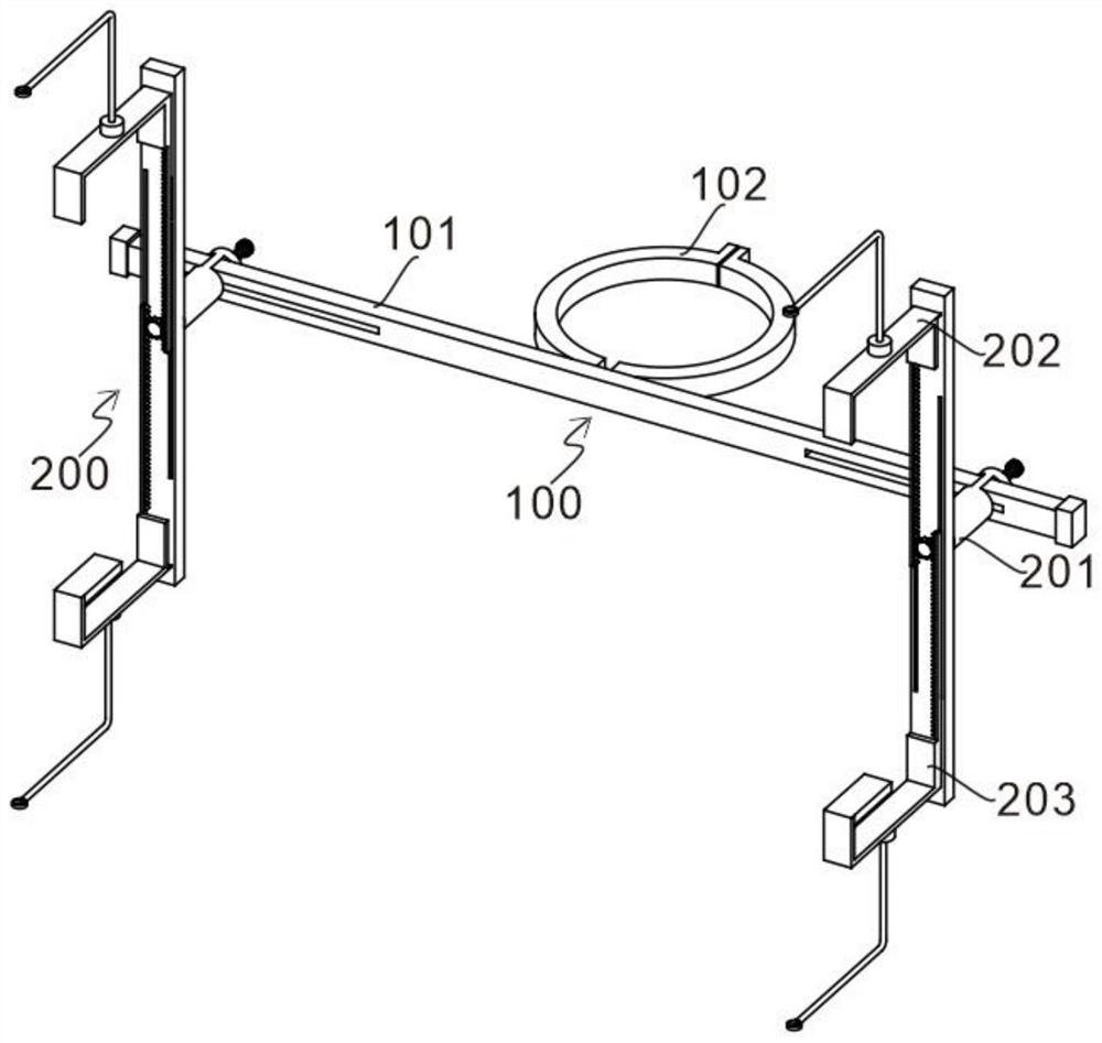
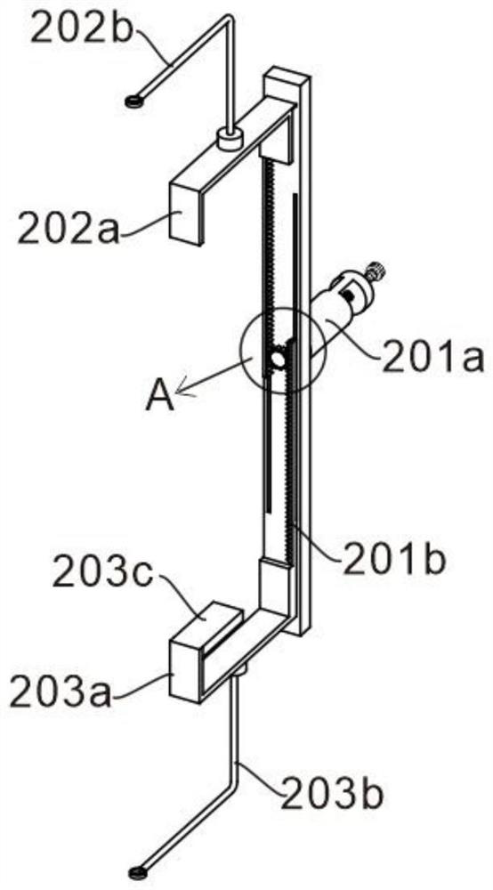
[0027] refer to figure 1 , is the first embodiment of the present invention, which provides a drain wire fixing device, which includes a pole fixing assembly 100, including a connecting rod 101 and a movable hoop 102, and the movable hoop 102 is arranged on the connecting rod 101 At the middle position, the pole fixing assembly 100 is used to fix the device on the outside of the pole; the cross arm fixing assembly 200, the cross arm fixing assembly 200 is used to fix the bypass device on the cross arm, including the displacement fixing part 201, the upper connection 202 and the lower connecting piece 203, the displacement fixing piece 201 is arranged at the end of the connecting rod 101, the displacement fixing piece 201 is used to adjust the fixed position of the device on the cross arm, and the upper connecting piece 202 and the lower connecting piece 203 are respectively set at the displacement The upper and lower ends of the fixing part 201, the upper connecting part 202 a...

Embodiment 2

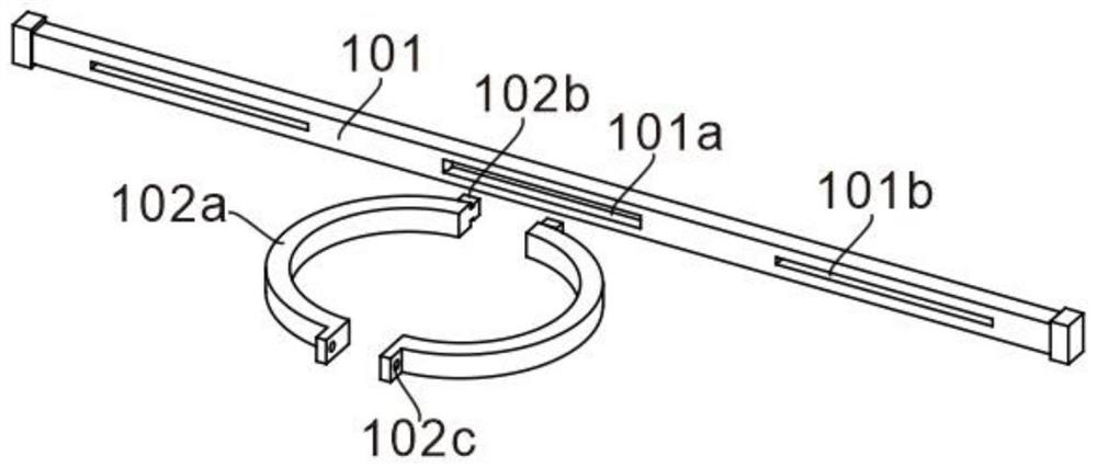
[0031] refer to Figure 1 to Figure 7 , is the second embodiment of the present invention, and it is different from the first embodiment in that: a first sliding groove 101a is provided at the middle position of the connecting rod 101, and the movable hoop 102 includes two groups of semicircular hoops 102a, the semicircular hoops 102a is disposed in the first sliding slot 101a through the slider 102b. A bolt connection hole 102c is provided at the end of the semicircular hoop 102a away from the slider 102b.

[0032] Two sets of semi-circular hoops 102a realize cohesion and fixation of electric poles of any diameter. By moving the slider 102b located in the first chute 101a, the cohesion diameter of the semi-circular hoops 102a can be changed to adapt to poles of different diameters. Through the semi-circular hoops The bolt connection holes 102c provided on the strips 102a fix the two sets of semicircular hoops 102a together and hold the pole tightly, so that the whole device ...


PUM


Abstract

The invention discloses a drainage wire fixing device, and the device comprises an electric pole fixing assembly which comprises a connecting rod and a movable hoop, and the movable hoop is disposed in the middle of the connecting rod; the cross arm fixing assembly comprises a displacement fixing piece, an upper connecting piece and a lower connecting piece, the displacement fixing piece is arranged at the end of the connecting rod, and the upper connecting piece and the lower connecting piece are movably arranged at the upper end and the lower end of the displacement fixing piece respectively. According to the device, the drainage wire is conveniently and rapidly fixed through the electric pole fixing assembly and the cross arm fixing assembly, the whole device is installed on the outer side of an electric pole through the electric pole fixing assembly, the fixing position and height of the drainage wire are flexibly adjusted through the cross arm fixing assembly, and the device is suitable for fixing the external drainage wire of a single-cross-arm or double-cross-arm electric pole.

Description

technical field [0001] The invention relates to the technical field of drainage wire fixing, in particular to a drainage wire fixing device. Background technique [0002] In the power line, when the user needs to take power from the main line for use, it needs to connect the main line to the user terminal through the drain line. Since the main line is at a high place and the user end is at a low place, the drain line is connected from a high place to a low place. To avoid the influence of the gravity of the drain wire itself on the reliability of the terminal connection, or to avoid the large impact of the wind on the drain wire terminal in strong winds, it is necessary to bind the middle part of the drain wire to the insulator with an aluminum wire; In the operating procedures, it is stipulated that several rounds of binding are required to maintain the reliability of the binding; the entire binding process is carried out in mid-air, and the binding round after round is not...

Claims


Application Information

Patent Timeline
Patent Type & Authority Applications(China)
IPC IPC(8): H02G7/05
CPCH02G7/05
Inventor 张洋何浪罗国鹏瞿灿沈德禹肖勇陈勇超
Owner GUIZHOU POWER GRID CO LTD
Why Eureka
Try Eureka