Electronic locking core limiting self-locking clutch device

A clutch device, self-locking technology, applied in the field of locks, can solve the problem that the clutch and the tongue can not be well connected, and achieve the effect of improving wear resistance

Pending Publication Date: 2018-12-18
YANGZHOU ANXINZHI TECH CO LTD
View PDF0 Cites 0 Cited by
  • Summary
  • Abstract
  • Description
  • Claims
  • Application Information

AI Technical Summary

Problems solved by technology

[0003] The purpose of the present invention is to provide an electronic lock cylinder limit self-locking clutch device, which solves the technical problem that the clutch and the tongue in the prior art cannot be well engaged

Method used


Image

  • Electronic locking core limiting self-locking clutch device
  • Electronic locking core limiting self-locking clutch device
  • Electronic locking core limiting self-locking clutch device

Examples


Embodiment 1

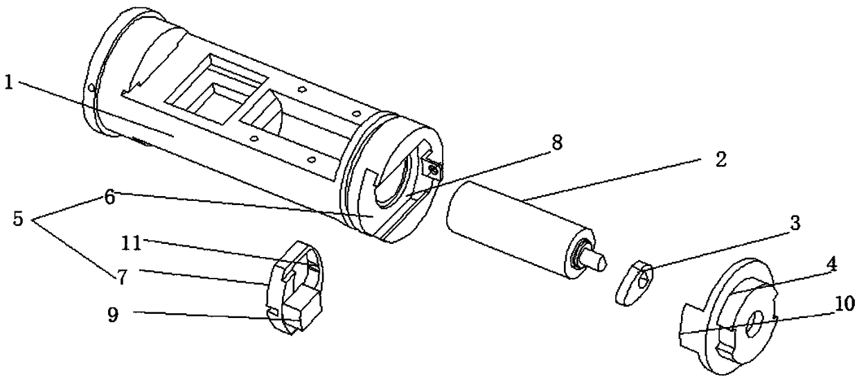
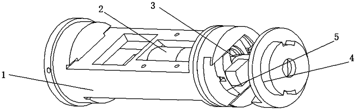
[0021] Such as Figure 1-2 As shown, an electronic lock cylinder limit self-locking clutch device provided by the present invention includes a lock core 1, a driving device 2, a toggle block 3 and a dial tongue 4, and the lock core 1 is internally provided with a driving device 2 , and the end of the lock core 1 is provided with a clutch mechanism 5, the toggle block 3 is installed at the end of the drive device 2, and the toggle block 3 is located inside the clutch mechanism 5, and the toggle tongue 4 is installed on the lock core 1, and the toggle tongue 4 is located outside the clutch mechanism 5, and the driving device 2 can be a motor, which provides power to drive the toggle block 3 to rotate.

[0022] Wherein, the clutch mechanism 5 includes a clutch groove 6 and a clutch block 7, the clutch groove 6 is opened at the end of the lock core 1, the clutch block 7 is located inside the clutch groove 6, and the outside of the clutch groove 6 is The side is provided with a gr...

Embodiment 2

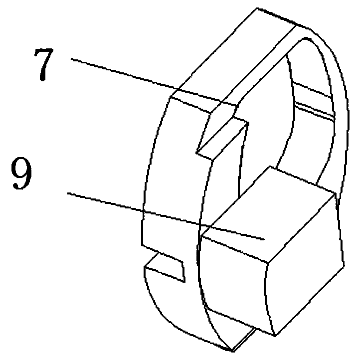
[0029] Based on Example 1, such as image 3 As shown, the outer surface of the clutch boss 9 is an arc surface, which can ensure that the outer surface of the clutch boss 9 is consistent with the circumferential surface of the end of the lock core. The inner wall of the block 10 may interfere, so as to ensure a sufficiently large contact surface and improve wear resistance.


PUM


Abstract

The invention discloses an electronic locking core limiting self-locking clutch device. The electronic locking core limiting self-locking clutch device comprises a locking core, a driving device, a pushing block and a pushing tongue. A driving device is arranged inside the locking core, and a clutch mechanism is arranged on the end portion of the locking core. The pushing block is installed on theend portion of the driving device, and the pushing block is located inside the clutch mechanism. The pushing tongue is installed on the end portion of the locking core, and the pushing tongue is located on the outer side of the clutch mechanism. The electronic locking core limiting self-locking clutch device solves the technical problem that a clutch and a pushing tongue cannot be well connectedin the prior art.

Description

technical field [0001] The invention relates to the technical field of locks, in particular to an inner rotating shaft of an electronic lock cylinder. Background technique [0002] In daily life, with the wide application of electronic locks, its safety and convenience are higher than traditional mechanical locks, and the stability of the clutch of electronic locks directly affects the safety of the lock itself. If the clutch cannot be disengaged from the dial, the door lock will be in the open state and can be opened at will, causing economic losses to the user and even endangering the safety of life. If the clutch cannot engage the dial or is not tightly engaged with the dial, it will cause the door lock to fail to open and increase the difficulty for the user to open. Contents of the invention [0003] The purpose of the present invention is to provide a self-locking clutch device for limiting the position of the electronic lock cylinder, which solves the technical pro...

Claims


Application Information

Patent Timeline
Patent Type & Authority Applications(China)
IPC IPC(8): E05B47/00E05B15/00
CPCE05B15/00E05B47/0012E05B47/0607E05B2047/0026
Inventor 赵霄骁
Owner YANGZHOU ANXINZHI TECH CO LTD
Why Eureka
Try Eureka