
Downhole injection device being able to change polymer viscosity

An injection device, polymer technology, applied in wellbore/well components, production fluids, earthwork drilling, etc., can solve problems such as different polymer viscosity requirements, affecting polymer utilization efficiency, changing polymer viscosity, etc., to reduce Operational cost, effect of increasing injection efficiency and utilization efficiency, increasing the scope of application

Active Publication Date: 2018-12-18
CHINA NAT OFFSHORE OIL CORP +1
View PDF9 Cites 1 Cited by
  • Summary
  • Abstract
  • Description
  • Claims
  • Application Information

AI Technical Summary

Problems solved by technology

[0006] In summary, the current offshore polymer injection measurement and adjustment technology and tools can meet the requirements of layered polymer injection deployment, but they cannot meet the needs of changing polymer viscosity according to geological requirements. The problem of different viscosity requirements has always existed, which affects the utilization efficiency of the polymer injected downhole. Therefore, in order to solve the above problems, it is necessary to propose a variable viscosity injection polymer measurement and adjustment device.

Method used


Image

  • Downhole injection device being able to change polymer viscosity
  • Downhole injection device being able to change polymer viscosity
  • Downhole injection device being able to change polymer viscosity

Examples


Embodiment Construction

[0019] In order to further understand the invention content, characteristics and effects of the present invention, the following examples are given, and detailed descriptions are as follows in conjunction with the accompanying drawings:

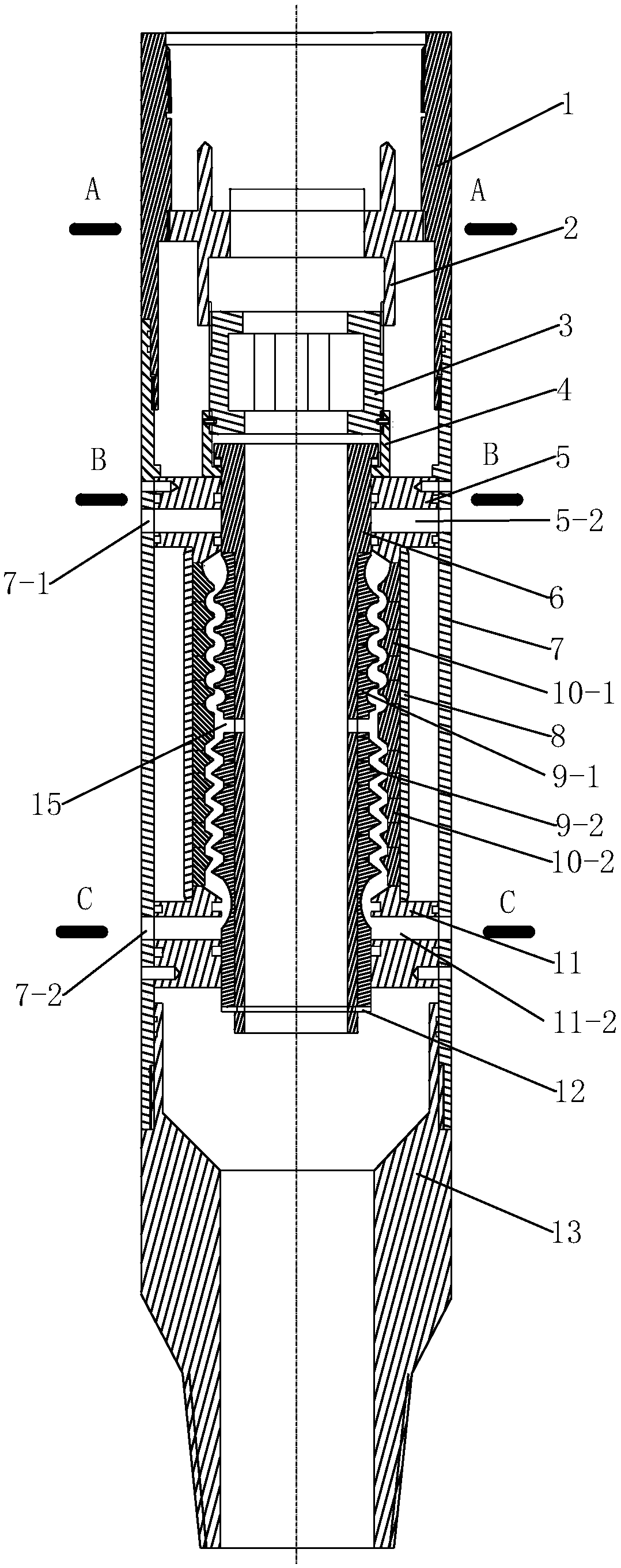
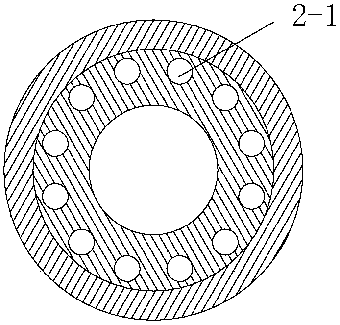
[0020] see Figure 1 to Figure 7 , a downhole injection device capable of changing polymer viscosity, comprising an upper joint 1, an outer casing 7 and a lower joint 13 sequentially connected from top to bottom, and a viscosity-preserving liquid outlet is provided on the side wall of the outer casing 7 7-1 and viscosity reducing liquid outlet 7-2.

[0021] A guiding and positioning component 2 is fixedly connected inside the upper joint 1 , and the guiding and positioning component 2 is provided with an introduction pen tip structure and a positioning structure.

[0022] Inside the outer casing 7, there is a dispensing adjustment mechanism integrating the functions of maintaining viscosity and reducing viscosity. The dispensing adjustment m...


PUM


Abstract

The invention discloses a downhole injection device being able to change polymer viscosity. The downhole injection device being able to change polymer viscosity includes successively connected upper joint, outer sleeve tube and lower joint from top to bottom, wherein a viscosity maintaining liquid outlet and a viscosity reducing liquid outlet are arranged on the side wall of the outer sleeve tube;a guiding and positioning component is fixedly connected to the upper joint; an injection allocation adjusting mechanism integrated with viscosity maintaining and viscosity reducing functions is arranged in the outer sleeve tube; the injection allocation adjusting mechanism is provided with a viscosity maintaining annular channel and a viscosity reducing annular channel; an axial section of the viscosity maintaining annular channel is an arc wave, and an axial section of the viscosity reducing annular channel is an sharp toothed wave; and a polymer liquid inlet communicating with the viscosity maintaining annular channel and the viscosity reducing annular channel is arranged on a central tube. The downhole injection device being able to change polymer viscosity can inject the polymer withdifferent injection allocation amounts and different viscosities in different layers according to the reservoir geological requirements in the process of layered polymer injection and allocation process for polymer injection wells in the offshore oilfield, and can solve the problem that different polymer viscosity demands of the polymer injection layers in the same well, thus improving the injection efficiency and the utilization efficiency of the polymer, reducing the operating cost, and realizing yield increase and injection increase in the offshore oilfield.

Description

technical field [0001] The invention relates to a layered polymer injection tool for offshore oil production technology, in particular to a layered polymer injection measuring and adjusting work cylinder with the function of changing viscosity. Background technique [0002] Polymer flooding is an important technical means to achieve "increased and high production" in offshore oilfields. At present, the polymer injection technology used in offshore oilfields is gradually changing from general injection and multi-tube separate injection to single-tube layered polymer injection measurement and adjustment technology, and the measurement and adjustment and monitoring methods are gradually changing from mechanization to semi-automation and automation. Fine interlayer injection can reduce the influence of interlayer heterogeneity and improve injection efficiency. However, in view of the different polymer viscosity requirements of the formation, the matching injection polymer measur...

Claims


Application Information

Patent Timeline
Patent Type & Authority Applications(China)
IPC IPC(8): E21B43/22
CPCE21B43/16
Inventor 牛贵锋杨万有刘敏黄泽超王良杰毛庆凯
Owner CHINA NAT OFFSHORE OIL CORP
Learn More