
A Passive Time-Difference Location Method of High Repetition Frequency Pulse Signal

A pulse signal, time difference positioning technology, applied in positioning, radio wave measurement systems, instruments, etc., can solve problems such as time difference blur, and achieve the effect of fast positioning speed, strong practicability, and low frequency difference extraction accuracy requirements.

Active Publication Date: 2020-11-20
XIAN INSTITUE OF SPACE RADIO TECH
View PDF8 Cites 0 Cited by
  • Summary
  • Abstract
  • Description
  • Claims
  • Application Information

AI Technical Summary

Problems solved by technology

[0005] The technical problem of the present invention is: to overcome the deficiencies of the prior art, to provide a high repetition frequency pulse signal passive time difference positioning method, to solve the time difference ambiguity problem in the long baseline high repetition frequency pulse signal positioning, to meet the high repetition frequency Positioning requirements for pulse signals

Method used


Image

  • A Passive Time-Difference Location Method of High Repetition Frequency Pulse Signal
  • A Passive Time-Difference Location Method of High Repetition Frequency Pulse Signal
  • A Passive Time-Difference Location Method of High Repetition Frequency Pulse Signal

Examples


Embodiment Construction

[0040] Specific embodiments of the present invention will be further described in detail below in conjunction with the accompanying drawings.

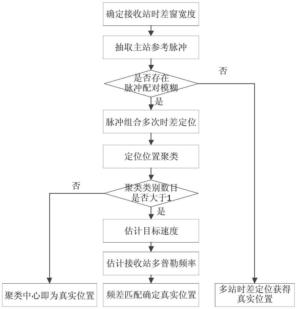
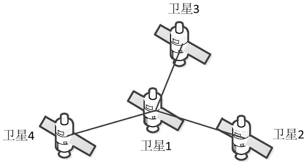
[0041] The general process of the present invention is as figure 1 As shown, the receiving station takes the satellite as an example, such as figure 2 As shown in the figure, Y-shaped stations are adopted, the central satellite is the main satellite, and the baseline length is 2000Km. The reconnaissance receiving range of the satellite is a circle with a radius of 2000Km. The speed is 77m / s, the initial position is (1100, 0, 6285) Km, and the pulse emission frequency of the radiation source is assumed to be 30KHz.

[0042] The implementation steps are as follows:

[0043] 1) Determine the width of the time difference window corresponding to each secondary receiving station, and the width of the time difference window is the difference between the maximum value and the minimum value of the time difference formed between the secondar...


PUM


Abstract

The invention discloses a passive time difference of arrival positioning method based on high repetition frequency pulse signals. The invention obtains a true position solution by estimating speed ofa target radiation source, combining a known position and speed of receiving station, and correspondingly eliminating false fuzzy solutions by frequency difference; simultaneously solve a problem of pulse pairing of high repetition frequency radar signals between moving target and stationary target without adding device, which has characteristics of short accumulation time and fast positioning speed.

Description

technical field [0001] The invention relates to a passive time-difference positioning method of a high repetition frequency pulse signal, belonging to the technical field of passive positioning. Background technique [0002] Passive reconnaissance and positioning play an extremely important role in electronic countermeasures. Among them, time difference positioning uses the time difference of the same radiation source pulse signal to reach multiple stars to form a hyperboloid for positioning. Due to its high positioning accuracy and simple positioning algorithm, long-baseline time-of-flight positioning has been widely used in engineering realization. However, when the baseline between the system stations is long, the time difference between the arrival of the same target signal at different receiving stations is relatively large, so the pulse pairing ambiguity problem exists in the long baseline time difference system, especially when the pulse signal of the radiation source...

Claims


Application Information

Patent Timeline
Patent Type & Authority Patents(China)
IPC IPC(8): G01S5/02
CPCG01S5/02
Inventor 方海杨旭段崇棣白琳陈显舟
Owner XIAN INSTITUE OF SPACE RADIO TECH
Learn More