
Electronic connector

An electronic connector and electrical connection technology, which is applied in the direction of connection and connection device components, circuits, etc., can solve the problems that signals are easy to crosstalk each other and affect the use, and achieve the effect of reducing signal crosstalk

Pending Publication Date: 2018-12-18
SHENZHEN GLGNET ELECTRONICS
View PDF13 Cites 0 Cited by
  • Summary
  • Abstract
  • Description
  • Claims
  • Application Information

AI Technical Summary

Problems solved by technology

However, the signals of data transmission modules in adjacent slots are likely to crosstalk each other, affecting the use of

Method used


Image

  • Electronic connector
  • Electronic connector
  • Electronic connector

Examples


Embodiment Construction

[0022] Below, the present invention will be further described in conjunction with the accompanying drawings and specific implementation methods. It should be noted that, under the premise of not conflicting, the various embodiments described below or the technical features can be combined arbitrarily to form new embodiments. .

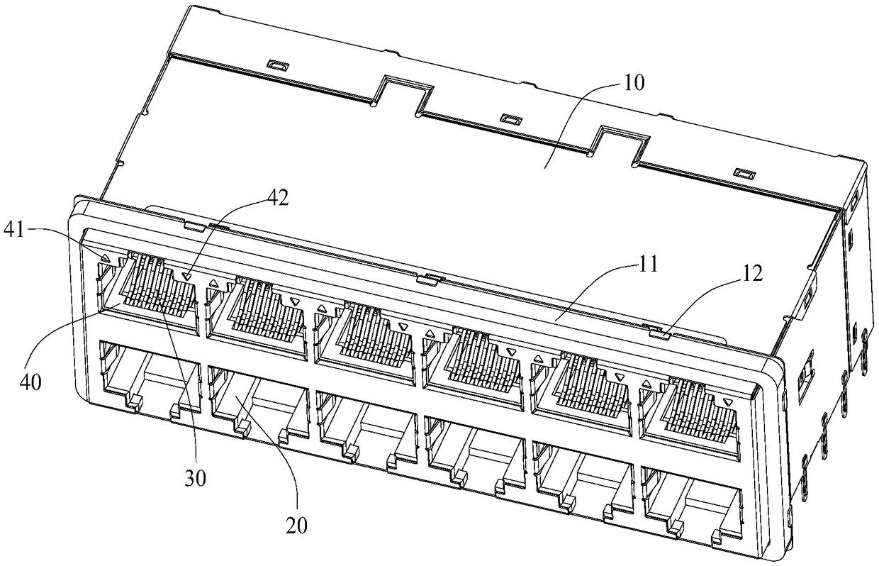
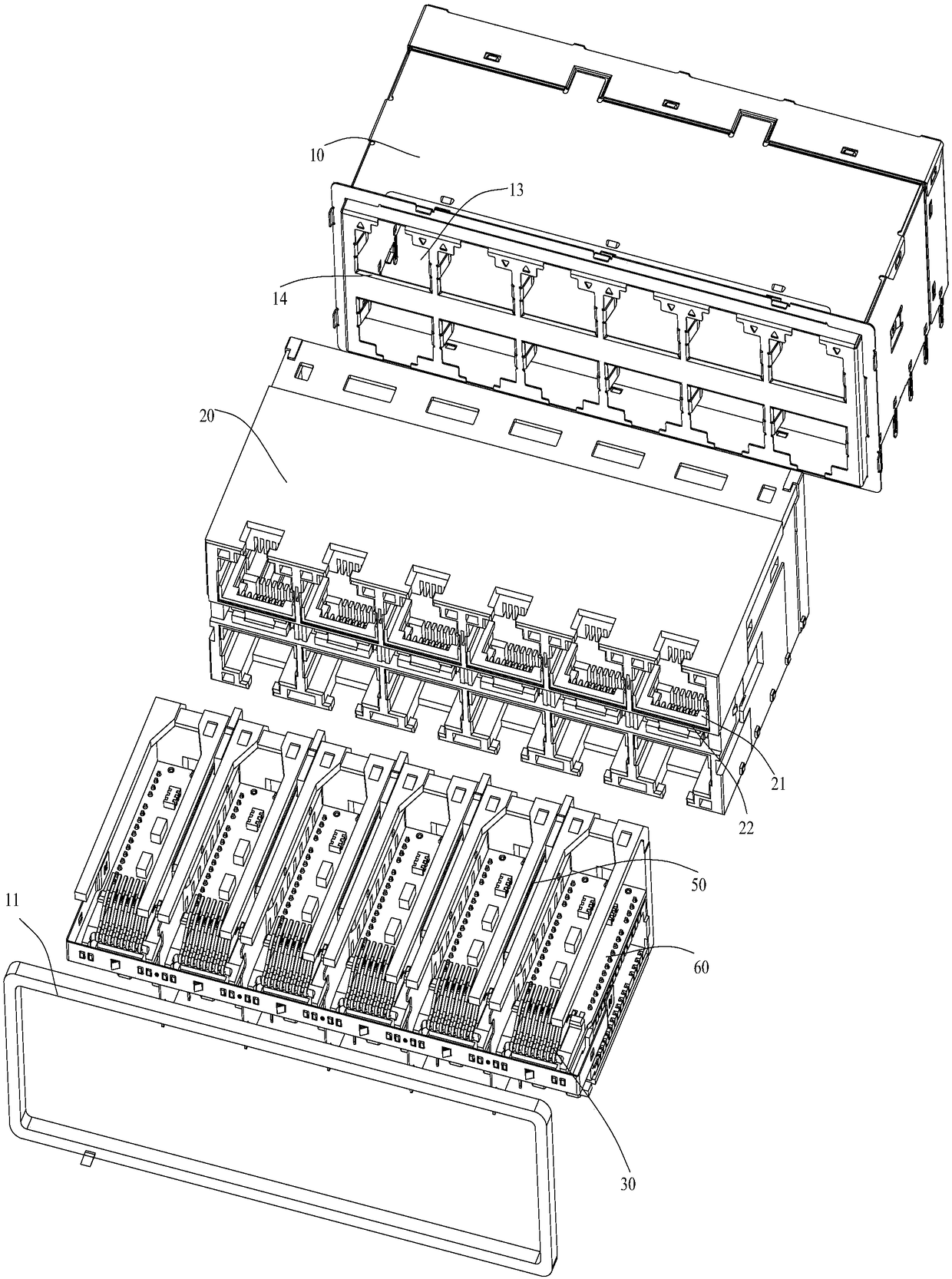
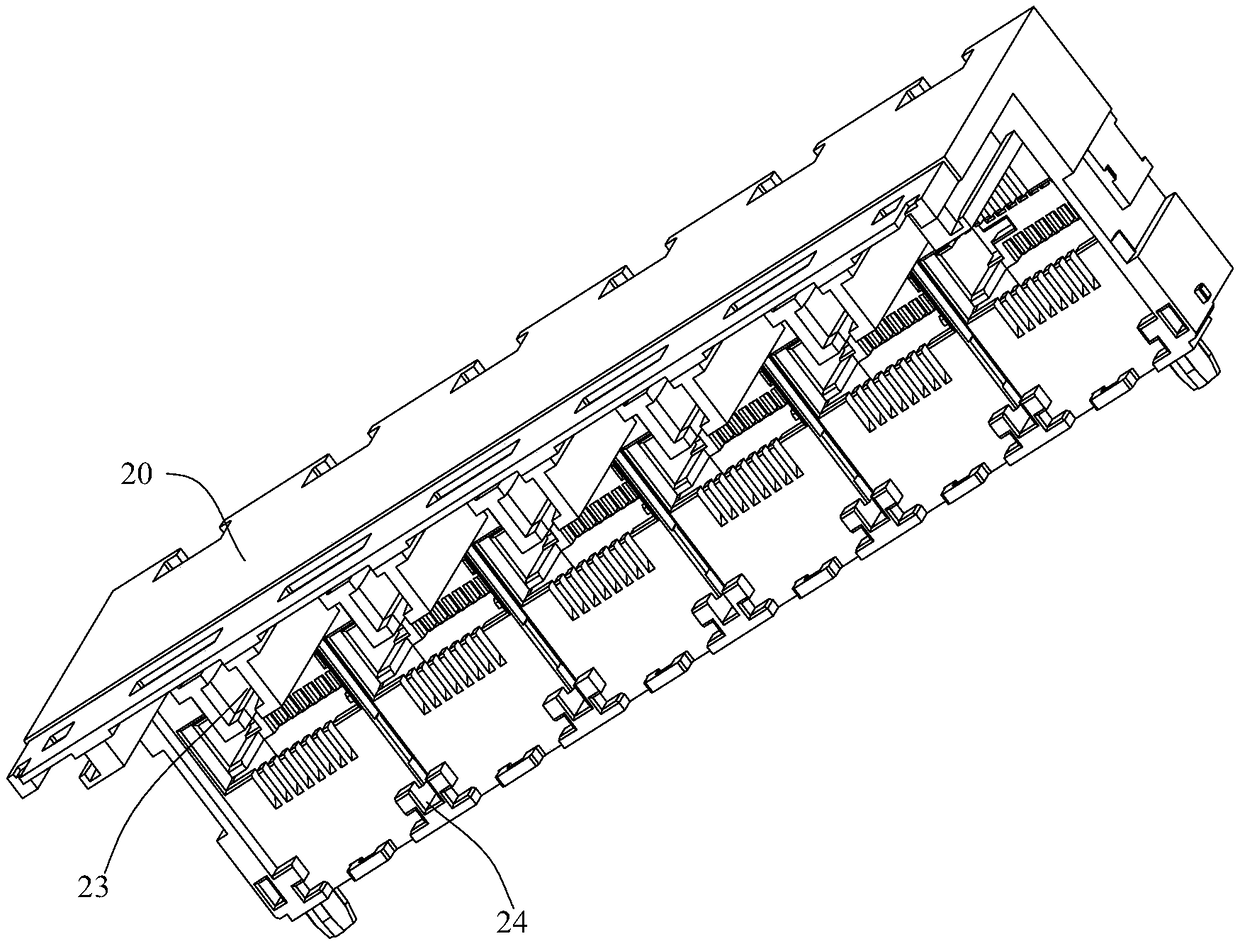
[0023] Such as Figure 1-4 The shown electronic connector includes a shielding shell 10, a plastic housing 20 and a plurality of data transmission modules 30; the plastic housing 20 is provided with a plurality of slots with a first socket 21; a plurality of data transmission modules The modules 30 are inserted into a plurality of slots in one-to-one correspondence; the shielding shell 10 is wrapped on the outside of the plastic shell 20; the shielding shell 10 is provided with a plurality of second sockets 13, and the multiple second sockets 13 are connected to a plurality of The first sockets 21 of the slots are in one-to-one correspondence and form...


PUM


Abstract

The invention discloses an electronic connector, which comprises a shielding housing, a plastic housing and a plurality of data transmission modules. The plastic housing is provided with a plurality of slots with a first socket; A plurality of data transmission modules are inserted into a plurality of slots one by one correspondingly; The shielding shell is wrapped on the outside of the plastic shell; The shield housing is provided with a plurality of second sockets, and the plurality of second sockets correspond to the first sockets of the plurality of sockets one by one and form an interfacefor plug-in of a connector of an external device. A plurality of slots are spaced apart along the length direction of the plastic housing; A signal shielding plate is arranged between two adjacent slots, and a terminal is arranged at the bottom end of the signal shielding plate, and the terminal protrudes from the bottom end face of the plastic housing through the bottom end face of the shieldinghousing. An electronic connector of the present invention reduces signal crosstalk of a data transmission module in two adjacent slots.

Description

technical field [0001] The invention relates to an electronic connector. Background technique [0002] At present, electronic connectors have become a necessary device for computers, routers and other network equipment. It mainly includes a housing made of plastic materials, a data transmission module inserted in the plastic housing, and a shielding shell made of metal materials wrapped outside the plastic housing, and the data transmission module generally has multiple The connection terminals are embedded side by side on the connection base to form. Specifically, the first socket is set on the plastic shell corresponding to the position of the data transmission module, and the second socket is correspondingly set on the shielding shell wrapped outside the plastic shell, and the second socket is correspondingly set on the outside of the first socket, so in The electronic connector can then form an interface formed by corresponding matching of the first socket and the seco...

Claims


Application Information

Patent Timeline
Patent Type & Authority Applications(China)
IPC IPC(8): H01R13/648H01R13/6586
CPCH01R13/648H01R13/6586
Inventor 杨冰
Owner SHENZHEN GLGNET ELECTRONICS
Learn More