A Transient Stability Identification Method Based on Voltage Trajectory Characteristics
A technology of transient stability and identification method, which is applied in the direction of electrical components, circuit devices, AC network circuits, etc., and can solve problems such as system model and parameter deviation, and affecting the accuracy of calculation results
- Summary
- Abstract
- Description
- Claims
- Application Information
AI Technical Summary
Problems solved by technology
Method used
Image
Examples
Embodiment 1
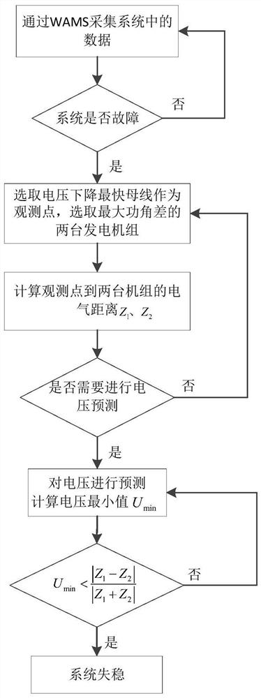
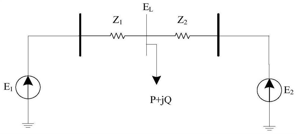
[0037] Embodiment 1: as Figure 1-3 As shown, a transient stability identification method based on the characteristics of the voltage trajectory collects the information of the bus node in the power system at a certain moment through the wide-area measurement system; judges whether the power system has a fault, and if a fault occurs, select the fastest voltage drop The bus node of the observation point is used as the observation point; select the two units with the largest generator power angle difference, and calculate the electrical distance from the observation point to the two units; predict the future voltage according to the historical data of the observation point voltage; The relationship between the minimum value of and the electrical distance can be used to judge whether the power angle instability of the system occurs.
[0038] The specific steps are:
[0039] Step S1: At time t, collect the power angle δ of the i-th generator in the power system in real time throu...
Embodiment 2
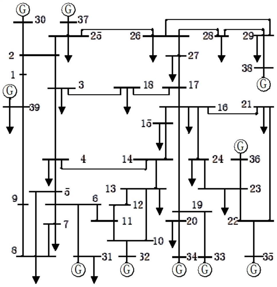
[0050] Embodiment 2: In order to verify the stability identification method based on phase trajectory and transient energy proposed in this paper, the BPA program is used to simulate the same fault at different locations and the different duration of the same fault on the IEEE10 machine 39 node system. The calculation step is 0.01s, and the generator uses E q'Model. The operation mode is 80% constant impedance and 20% constant current load at the 4th busbar, 70% constant impedance and 30% constant current load at the 7th busbar, and 50% constant impedance and 30% constant current load at the 15th busbar. Constant current, 20% constant power load, 30% constant impedance, 70% constant power load at the bus bar 23 . The fault is set as a three-phase short-circuit fault occurs at 0s on the line connected from bus 26 to bus 29, and the line is cut off at 0.28s.
[0051] Step S1, at time t, collect the power angle of the th generator and the voltage of the qth bus node in the powe...
Embodiment 3
[0057] Embodiment 3: In order to verify the stability identification method based on phase trajectory and transient energy proposed in this paper, the BPA program is used to simulate the same fault at different locations and the different duration of the same fault on the IEEE10 machine 39 node system. The calculation step is 0.01s, and the generator uses E q 'Model. The operation mode is 80% constant impedance and 20% constant current load at the 4th busbar, 70% constant impedance and 30% constant current load at the 7th busbar, and 50% constant impedance and 30% constant current load at the 15th busbar. Constant current, 20% constant power load, 30% constant impedance, 70% constant power load at the bus bar 23 . The fault is set as a three-phase short-circuit fault occurs in the line connected from bus 26 to bus 29 at 0s, and the line is cut off at 0.20s.
[0058] Step S1, at time t, collect the power angle of the th generator and the voltage of the qth bus node in the pow...
PUM
 Abstract
Description
Claims
Application Information
 - R&D
- Intellectual Property
- Life Sciences
- Materials
- Tech Scout
- Unparalleled Data Quality
- Higher Quality Content
- 60% Fewer Hallucinations
Browse by: Latest US Patents, China's latest patents, Technical Efficacy Thesaurus, Application Domain, Technology Topic, Popular Technical Reports.
© 2025 PatSnap. All rights reserved.Legal|Privacy policy|Modern Slavery Act Transparency Statement|Sitemap|About US| Contact US: help@patsnap.com


