Method and device for detecting eye sight line, equipment and storage medium
A line of sight, eye technology, applied in the field of line of sight detection, can solve the problem of inability to obtain accurate line of sight data, and achieve the effect of improving accuracy
- Summary
- Abstract
- Description
- Claims
- Application Information
AI Technical Summary
Problems solved by technology
Method used
Image

Examples
Embodiment 1
[0040] Eye tracking, also known as gaze tracking, is the technique of estimating the line of sight and / or gaze of the eye by measuring eye movement. Wherein, the line of sight can be understood as a three-dimensional vector, and the gaze point can be understood as the two-dimensional coordinates of the projection of the three-dimensional vector on a certain plane.
[0041] In this embodiment, the tracking of eyeballs can be realized by using an optical recording method. The principle of the optical recording method is to use a camera or a video camera to record the eye movement of the subject, that is, to obtain an eye image that can reflect the eye movement, and extract eye features from the acquired eye image to establish a line of sight / fixation point estimation model. Wherein, the eye features may include: pupil position, pupil shape, iris position, iris shape, eyelid position, eye corner position, spot position (or Purchin's spot), etc.
[0042] Optical recording method...
Embodiment 2
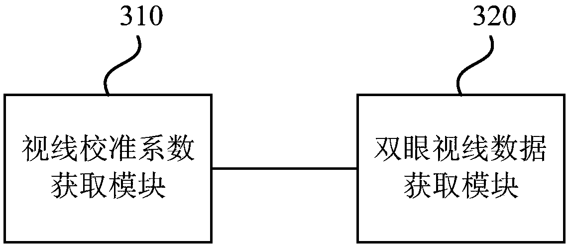
[0072] image 3 It is a schematic structural diagram of an eye sight detection device provided in Embodiment 2 of the present invention. Such as image 3 As shown, the device includes: a vision calibration coefficient acquisition module 310 and a binocular vision data acquisition module 320 .
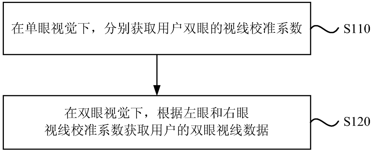
[0073] The line-of-sight calibration coefficient acquisition module 310 is used to respectively obtain the line-of-sight calibration coefficients of both eyes of the user under monocular vision, and the line-of-sight calibration coefficients include left-eye line-of-sight calibration coefficients and right-eye line-of-sight calibration coefficients;
[0074] The binocular sight data acquisition module 320 is configured to acquire the user's binocular sight data according to the left eye and right eye sight calibration coefficients under binocular vision.
[0075] Optionally, a detection result acquisition module is also included, which is used to compare the binocular sight data with ...
Embodiment 3
[0091] Figure 4 A schematic structural diagram of a mobile device provided by Embodiment 3 of the present invention, such as Figure 4As shown, a mobile device provided in this embodiment includes: a processor 41 and a memory 42 . The processor in the mobile device can be one or more, Figure 4 Taking a processor 41 as an example, the processor 41 and the memory 42 in the mobile device can be connected through a bus or other methods, Figure 4 Take connection via bus as an example.
[0092] The processor 41 of the mobile device in this embodiment integrates the eye sight detection device provided in the above embodiments. In addition, the memory 42 in the mobile device, as a computer-readable storage medium, can be used to store one or more programs, and the programs can be software programs, computer-executable programs and modules, such as the eye sight in the embodiment of the present invention. The program instruction / module corresponding to the detection method. The...
PUM
 Abstract
Description
Claims
Application Information
 - R&D Engineer
- R&D Manager
- IP Professional
- Industry Leading Data Capabilities
- Powerful AI technology
- Patent DNA Extraction
Browse by: Latest US Patents, China's latest patents, Technical Efficacy Thesaurus, Application Domain, Technology Topic.
© 2024 PatSnap. All rights reserved.Legal|Privacy policy|Modern Slavery Act Transparency Statement|Sitemap