Soft self-locking mechanical arm

A manipulator and self-locking technology, applied in the field of manipulators, can solve problems such as unstable grasping, insufficient strength, and failure to complete

Active Publication Date: 2018-12-21
江苏凯能机械设备有限公司
View PDF5 Cites 4 Cited by
  • Summary
  • Abstract
  • Description
  • Claims
  • Application Information

AI Technical Summary

Problems solved by technology

[0002] Existing flexible manipulators usually use an air cavity inside the deformable material, and multiple drive chambers are set on one side of the air cavity. After the air source is introduced, the drive chamber expands to stretch the side wall of one side of the flexible manipulator. The manipulator bends to the other side. Because it uses flexible and bendable materials for grasping, it can grasp soft and fragile objects, but there are two problems with this type of manipulator: 1. The bending curve is fixed, for example, "a bow-shaped CN108381534 "flexible manipulator with continuous curved inner cavity. After the air source is introduced, the manipulator bends to achieve grasping, but the curved curve cannot adapt to the surface curve of the clay pot, and the point contact with the pottery pot makes the grasping unstable; 2. The strength itself is not enough. In order to complete the bending, the manipulator uses flexible materials, which are easily deformed when subjected to external forces, resulting in unstable grasping;
[0003] Since the handmade clay pots are fragile, the external curves of each pot are different, and the manipulators in the prior art cannot complete the grasping of the pots in the production of pots

Method used


Image

  • Soft self-locking mechanical arm
  • Soft self-locking mechanical arm
  • Soft self-locking mechanical arm

Examples


specific Embodiment approach 1

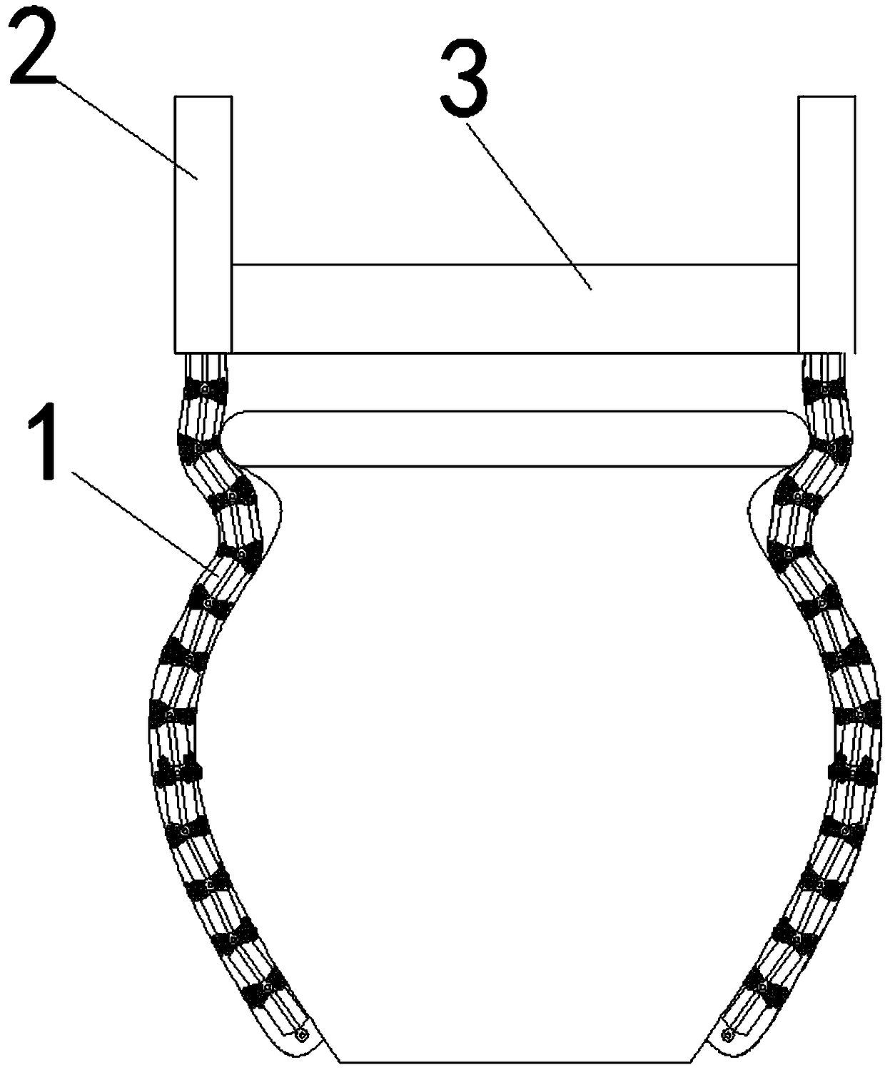
[0043] combine figure 1 As shown, a software self-locking manipulator disclosed in this embodiment includes: a manipulator joint 1, a joint accommodation bin 2, and a base 3. The base 3 is provided with several slideways, and several slideways are based on The center of the seat 3 is set as the center of the circle along the radially equally divided circle, and each of the slides is provided with a joint accommodation bin 2, and a plurality of manipulator joints 1 are arranged in the joint accommodation bin 2, and several manipulator joints 1 are hinged head to tail in sequence The connection forms a joint chain; the base 3 is used as the connection between the support and the lifting structure, and the position of the joint chain is adjusted through the joint accommodation chamber 2 on the base 3 to adapt to pottery pots of different shapes and sizes. to crawl;

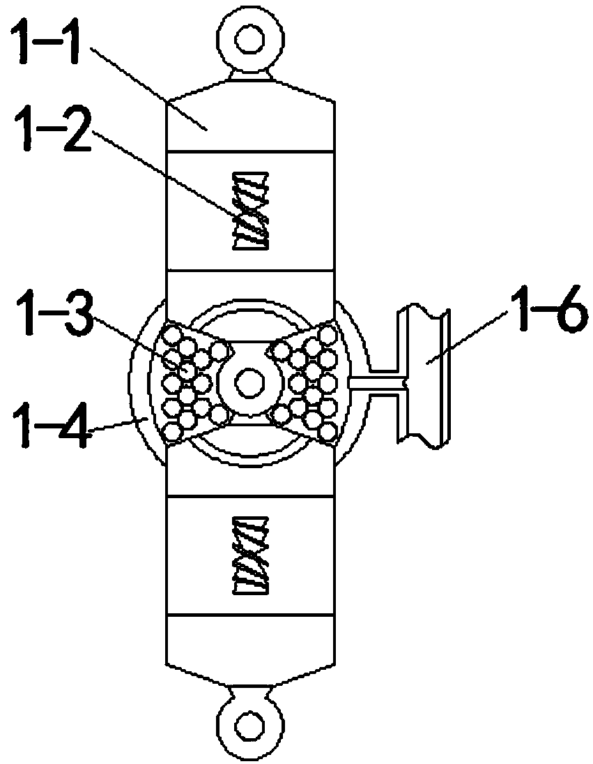
[0044] combine figure 2 As shown, the manipulator joint includes: a joint body 1-1, a fitting device 1-2, a fil...

specific Embodiment approach 2

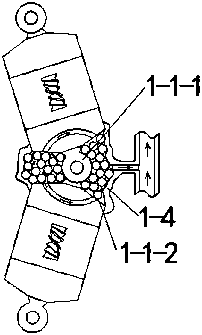
[0049] This embodiment is based on Embodiment 1. Specifically, the inner side of the cladding layer 1-4 is provided with a protruding end extending toward the hinge of the joint body 1-1. -4 when the filler 1-3 is squeezed, the protruding end pushes the filler 1-3 toward the pressure surfaces 1-1-2 on both sides.

specific Embodiment approach 3

[0050] This embodiment is based on the specific implementation mode 1 or 2. Specifically, the fillers 1-3 are several spherical fillers, and the spherical fillers are provided with through holes for ventilation. The cladding layer 1 The inner side of -4 is provided with a separation layer, the separation layer is a mesh structure, the spherical filling is arranged in the separation layer, and the separation layer covers the filling 1-3 without affecting the air flow. When the vacuum is drawn, the filler 1-3 is moved out of the cavity along with the cladding layer 1-4.


PUM


Abstract

The invention belongs to the technical field of mechanical arms, and particularly relates to a soft self-locking mechanical arm. The soft self-locking mechanical arm comprises mechanical arm joints, ajoint accommodating bin and a base, wherein the plurality of mechanical arm joints are sequentially connected end to end in a hinging mode to form a joint chain. The mechanical arm joints comprise joint bodies, bonding devices, fillers, coating layers and air pipes, wherein the hinged portions of the two joint bodies are provided with the coating layers. Extrusion surfaces are formed by the lateral sides, close to hinging rods, of the joint bodies. Two cavities of which the volumes change along with the rotating of the joint bodies are formed by the extrusion surfaces and the coating layers and are internally provided with the fillers correspondingly. The coating layers are connected with the air pipes. When a ceramic jar is grabbed, the joint chain can automatically adapt to the surfacecurve of the ceramic jar. After a grabbing structure with the lower end bunched is formed by the joint chain, extra pressure on the ceramic jar is avoided, and the shape of the joint chain is locked,so that the ceramic jar is grabbed. Meanwhile, due to the combination of the adaptability of a flexible mechanical arm and the strength of a rigid mechanical arm, grabbing of the ceramic jar is realized.

Description

technical field [0001] The invention belongs to the technical field of manipulators, in particular to a software self-locking manipulator. Background technique [0002] Existing flexible manipulators usually use an air cavity inside the deformable material, and multiple drive chambers are set on one side of the air cavity. After the air source is introduced, the drive chamber expands to stretch the side wall of one side of the flexible manipulator. The manipulator bends to the other side. Because it uses flexible and bendable materials for grasping, it can grasp soft and fragile objects, but there are two problems with this type of manipulator: 1. The bending curve is fixed, for example, "a bow-shaped CN108381534 "flexible manipulator with continuous curved inner cavity. After the air source is introduced, the manipulator bends to achieve grasping, but the curved curve cannot adapt to the surface curve of the clay pot, and the point contact with the pottery pot makes the gra...

Claims


Application Information

Patent Timeline
Patent Type & Authority Applications(China)
IPC IPC(8): B25J15/12
CPCB25J15/12
Inventor 赵洪清
Owner 江苏凯能机械设备有限公司
Why Eureka
Try Eureka