
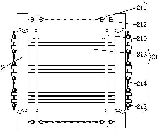
A cutting tool installation frame in a paper cutting device

A technology for cutting knives and paper cutting equipment, applied in the field of machinery, can solve the problems of inability to adjust the spacing of cutting knives, inconvenient installation or replacement of cutting knives, inability to install cutting knives, etc.

Active Publication Date: 2020-04-14
浏阳市金钩包装有限公司
View PDF5 Cites 0 Cited by
  • Summary
  • Abstract
  • Description
  • Claims
  • Application Information

AI Technical Summary

Problems solved by technology

[0002] In the production process of various paper products, it is necessary to cut the produced paper products into various sizes to meet different actual needs. This process requires the use of cutting equipment, but now It is extremely inconvenient to install or replace the cutting knives on some cutting equipment, and general cutting equipment cannot install cutting knives of different sizes according to different needs, nor can it adjust the distance between adjacent cutting knives. In order to achieve different sizes of paper according to different needs

Method used


Image

  • A cutting tool installation frame in a paper cutting device
  • A cutting tool installation frame in a paper cutting device
  • A cutting tool installation frame in a paper cutting device

Examples


Embodiment Construction

[0029] The following will clearly and completely describe the technical solutions in the embodiments of the present invention with reference to the accompanying drawings in the embodiments of the present invention. Obviously, the described embodiments are only some, not all, embodiments of the present invention. Based on the embodiments of the present invention, all other embodiments obtained by persons of ordinary skill in the art without making creative efforts belong to the protection scope of the present invention.

[0030] In describing the present invention, it should be understood that the terms "center", "longitudinal", "transverse", "length", "width", "thickness", "upper", "lower", "front", " Orientation indicated by rear, left, right, vertical, horizontal, top, bottom, inside, outside, clockwise, counterclockwise, etc. The positional relationship is based on the orientation or positional relationship shown in the drawings, and is only for the convenience of describin...


PUM


Abstract

The invention relates to the technical field of machines, in particular to a cutting tool installing frame in paper cutting equipment. The cutting tool installing frame comprises a frame body. The frame body comprises two parallel vertical supporting plates and two parallel horizontal supporting plates arranged between the two vertical supporting plates. A first sliding groove is formed in each horizontal supporting plate. The cutting tool installing frame is provided with a tool clamping mechanism. Installation of cutting tools different in length and thickness can be achieved by adjusting the distance between two first clamping plates and the distance between two second clamping plates in each set. Through the manner, convenient mounting and dismounting of the cutting tools can be achieved. The second clamping plates move on the first clamping plates, the distance between every two adjacent sets of second clamping plates can be freely adjusted, the distance between the adjacent cutting tools is freely adjusted, and accordingly the requirement for cutting different sizes of paper according to different needs is met.

Description

technical field [0001] The invention relates to the field of mechanical technology, in particular to a cutting tool installation frame in paper cutting equipment. Background technique [0002] In the production process of various paper products, it is necessary to cut the produced paper products into various sizes to meet different actual needs. This process requires the use of cutting equipment, but now It is extremely inconvenient to install or replace the cutting knives on some cutting equipment, and general cutting equipment cannot install cutting knives of different sizes according to different needs, nor can it adjust the distance between adjacent cutting knives. In order to achieve different sizes of paper according to different needs. In view of this, we propose a cutting tool installation frame in paper cutting equipment. Contents of the invention [0003] The object of the present invention is to provide a cutting tool installation frame in a paper cutting devi...

Claims


Application Information

Patent Timeline
Patent Type & Authority Patents(China)
IPC IPC(8): B26D7/26
CPCB26D7/2614B26D7/2628
Inventor 张磊钱求索高顺高成方万漂张祥雷
Owner 浏阳市金钩包装有限公司
Learn More