
Prefabricated concrete frame dry joints

A prefabricated and concrete technology, applied in the direction of building and building structure, can solve the problem of poor ductility of joints, and achieve the effect of optimizing on-site installation and construction, clear force transmission path, and meeting the requirements of seismic performance

Active Publication Date: 2020-02-07
CHONGQING UNIV
View PDF12 Cites 0 Cited by
  • Summary
  • Abstract
  • Description
  • Claims
  • Application Information

AI Technical Summary

Problems solved by technology

[0004] In order to achieve the above purpose, the present invention provides a prefabricated concrete frame dry joint, which solves the problem of poor ductility of the joints caused by the rigid connection of the fully prefabricated beam-column and column-column joints in the prior art

Method used


Image

  • Prefabricated concrete frame dry joints
  • Prefabricated concrete frame dry joints
  • Prefabricated concrete frame dry joints

Examples


Embodiment Construction

[0034] The following will clearly and completely describe the technical solutions in the embodiments of the present invention with reference to the accompanying drawings in the embodiments of the present invention. Obviously, the described embodiments are only some, not all, embodiments of the present invention. Based on the embodiments of the present invention, all other embodiments obtained by persons of ordinary skill in the art without making creative efforts belong to the protection scope of the present invention.

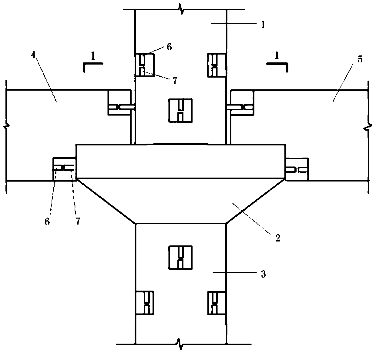
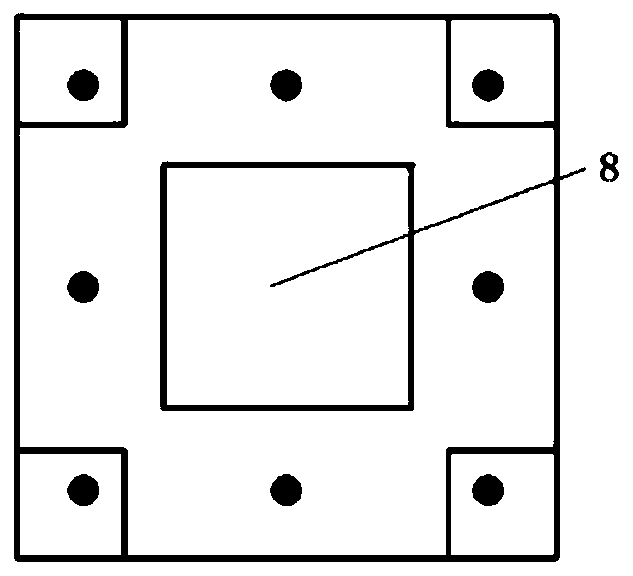
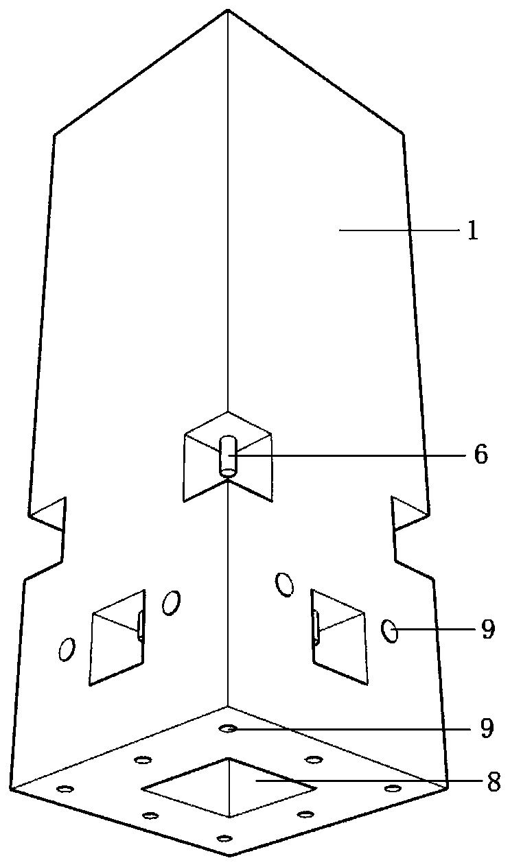
[0035] The prefabricated concrete frame dry joint of the present invention, such as Figure 1-Figure 5 As shown, it includes a prefabricated upper column 1, a prefabricated lower column 3, a prefabricated platform 2, a prefabricated left beam 4 and a prefabricated right beam 5, and the center of the top surface of the prefabricated lower column 3 and the bottom surface of the prefabricated upper column 1 are provided with a platform Core installation hole 8, t...


PUM


Abstract

The invention discloses a novel prefabricated concrete frame dry type joint which comprises an upper prefabricated column, a lower prefabricated column, a prefabricated cushion cap, a left prefabricated beam and a right fabricated beam. The centers of the top face of the lower fabricated column and the bottom face of the upper fabricated column are each provided with a cushion cap core installinghole, the prefabricated cushion cap is inserted into the cushion cap core installing hole in the top face of the lower fabricated column through the cushion cap at the bottom face, the cushion cap core at the top face of the prefabricated cushion cap is inserted into a cushion cap core installing hole in the bottom face of the upper prefabricated column, the horizontal ends of the left prefabricated beam and the right prefabricated beam are each provided with an upper end face and an inward lower end face, installing steel ribs are arranged at the inward lower end faces of the left prefabricated beam and the right prefabricated beam, and the left prefabricated beam and right prefabricated beam are inserted into steel reinforcing rib installing reserved holes of the side face of the prefabricated cushion cap. Shear force is transmitted through the bracket part of the cushion cap, the force transmission path of bending moment performed on concrete at the contact positions of longitudinalribs, beams-columns and the beam cushion cap is clear, and the structure is reliable.

Description

technical field [0001] The invention belongs to the technical field of building components, and relates to a dry joint of a prefabricated assembled concrete frame. Background technique [0002] According to the different construction methods of beam-column joints, prefabricated joint connection methods can be divided into wet connection and dry connection. Among them, wet connection is to complete the fabrication of beams, columns and other components in the factory in advance, and then transport the components to the site for assembly and hoisting. Concrete is poured at the beam-column joints to form the beam-column as a whole. The current methods of wet connection mainly include post-casting of node areas, integral prefabrication of nodes and world-structure systems. There is no post-casting tape for dry connection, and the components are completely prefabricated in the factory, and can be put into use after being assembled and hoisted on site. The commonly used dry conn...

Claims


Application Information

Patent Timeline
Patent Type & Authority Patents(China)
IPC IPC(8): E04B1/20E04B1/21
CPCE04B1/20E04B1/21
Inventor 曹永红杨佳东李国荣华建民曹晖
Owner CHONGQING UNIV
Learn More