Spray water type screw compressor

A screw compressor, water spray technology, applied in the field of compressors, can solve the problems of inconvenient installation and manufacture, small static and dynamic pressure difference, small axial force, etc., to achieve convenient installation and manufacture, good balance shaft The effect of axial force and good axial positioning

Pending Publication Date: 2018-12-21
NINGBO BAOSI ENERGY EQUIP
View PDF0 Cites 1 Cited by
  • Summary
  • Abstract
  • Description
  • Claims
  • Application Information

AI Technical Summary

Problems solved by technology

There are two kinds of structures: one of the structures is to place the axial thrust bearing between the rotor intake profile and the cylinder intake end surface; this structure has the following defects, due to the limitation of the rotor structure and center distance , usually only one axial thrust bearing can be arranged, and the size and force-bearing area are also limited, and the overall reliability is not high; another structure is to place two axial thrust bearings on the exhaust end face of the rotor; this kind of The structure has the following defects. Since the thrust bearing is designed on the exhaust end face, its static and dynamic pressure difference is small, and the axial force it can withstand is also small, so it cannot reach a higher operating pressure
The above two structures are relatively complicated and inconvenient to install and manufacture.

Method used


Image

  • Spray water type screw compressor

Examples


Embodiment Construction

[0024] The following are specific embodiments of the present invention and in conjunction with the accompanying drawings, the technical solutions of the present invention are further described, but the present invention is not limited to these embodiments.

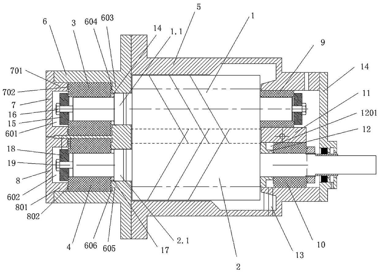
[0025] figure 1 It is a schematic cross-sectional structure diagram of the water-injected screw compressor of the present invention. The water-sprayed screw compressor of the present invention includes a fuselage, and a female rotor 1 and a male rotor 2 are arranged in the fuselage. The row end of the female rotor 1 is provided with a female row end sliding bearing 3, the row end of the male rotor 2 is provided with a male row end sliding bearing 4; the row end of the fuselage is provided with a first axial A limiting cavity and a second axial limiting cavity, the female row end sliding bearing 3 is arranged in the first axial limiting cavity, and the male row end sliding bearing 4 is arranged in the second axial limiting...


PUM


Abstract

The invention discloses a spray water type screw compressor. The spray water type screw compressor comprises a machine body, wherein a negative rotor and a positive rotor are arranged in the machine body; a negative row end sliding bearing is arranged at the row end of the negative rotor; a positive row end sliding bearing is arranged at the row end of the positive rotor; a first axial limiting cavity and a second axial limiting cavity are formed in the row end of the machine body, the negative row end sliding bearing is arranged in the first axial limiting cavity, and the positive row end sliding bearing is arranged in the second axial limiting cavity; negative water injection tanks are separately arranged at two ends of the negative row end sliding bearing and between two side walls of the first axial limiting cavity; and positive water injection tanks are separately arranged at two ends of the positive row end sliding bearing and between two side walls of the second axial limiting cavity. The spray water type screw compressor can enable the negative and positive rotors to bear more axial force, the structure is simple, and installation and manufacture are convenient.

Description

technical field [0001] The invention relates to the technical field of compressors, in particular to a water spray screw compressor. Background technique [0002] Screw compressor is a rotary volumetric machine with many advantages and is widely used. It has many advantages such as high reliability, small parts, less wearing parts, long life, stable operation, small vibration and high efficiency. Water-injected screw compressors are screw compressors that are lubricated by water. At present, the commonly used water spray screw host usually uses 4 radial sliding bearings plus 1~2 axial thrust bearings as the bearing support structure of the rotor. There are two kinds of structures: one of the structures is to place the axial thrust bearing between the rotor intake profile and the cylinder intake end surface; this structure has the following defects, due to the limitation of the rotor structure and center distance , usually only one axial thrust bearing can be arranged, and ...

Claims


Application Information

Patent Timeline
IPC IPC(8): F04C18/16F04C29/00F04C29/12
CPCF04C18/16F04C29/00F04C29/0021F04C29/12F04C2240/10F04C2240/50
Inventor 张炯焱
Owner NINGBO BAOSI ENERGY EQUIP
Why Eureka
Try Eureka