Small-flow high-lift centrifugal pump

A high-lift, centrifugal pump technology, applied to pumps, components of pumping devices for elastic fluids, pump control, etc., can solve problems such as impeller casting difficulties, low specific speed, low pump efficiency, etc., to improve efficiency, Improved coaxiality and ease of production and processing

Inactive Publication Date: 2016-07-06
湖南天一奥星泵业有限公司
View PDF8 Cites 0 Cited by
  • Summary
  • Abstract
  • Description
  • Claims
  • Application Information

AI Technical Summary

Problems solved by technology

[0002] In the field of fluid transportation, pumps are used in a wide range, with a flow rate ranging from a few tenths of a cubic meter to tens of thousands of cubic meters, and a head ranging from a few meters to several kilometers; Due to the low specific speed, it is difficult to cast the conventionally designed impeller and the cost is low. Most of them need to use the impeller to control the flow, but the existing impeller is difficult to control the flow, and the pump efficiency is very low.

Method used


Image

  • Small-flow high-lift centrifugal pump
  • Small-flow high-lift centrifugal pump
  • Small-flow high-lift centrifugal pump

Examples


Embodiment Construction

[0034] In order to enable those skilled in the art to better understand the technical solution of the present invention, the present invention will be described in detail below in conjunction with the accompanying drawings. The description in this part is only exemplary and explanatory, and should not have any limiting effect on the protection scope of the present invention. .

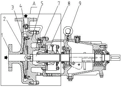
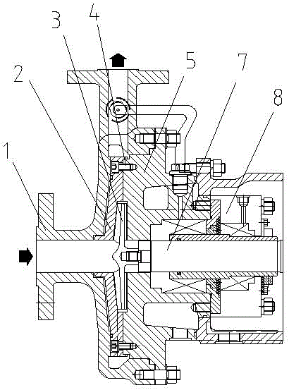
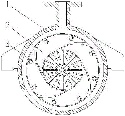
[0035] Such as Figure 1-Figure 7 As shown, the present invention is a small-flow high-lift centrifugal pump, which includes a pump body 1, a pump cover 5, a shaft 7, a mechanical seal 8, and a bearing suspension 9. The front end of the shaft 7 is sleeved with an impeller 3, The impeller 3 is arranged in the guide body 2 matched with it, the guide body 2 is fixed on the pump cover 5 by bolts 4, and the guide body 2 is evenly provided with a swirl shape as a whole and is connected with the impeller 3. The fluid inlet of the pump body 1 communicates with the guide body 2 , and the liquid outlet of the p...


PUM


Abstract

The present invention relates to the technical field of fluid conveying machinery, in particular to a small-flow high-lift centrifugal pump, which includes a pump body, a pump cover, a shaft, a mechanical seal, and a bearing suspension. The front end of the shaft is sleeved with an impeller. The above-mentioned impeller is arranged in the guiding body matched with it, and the said guiding body is fixed on the pump cover through bolts, and the said guiding body is evenly provided with a flow channel which is in the shape of a vortex and communicates with the impeller. The liquid inlet of the pump body is connected with the guide body, and the liquid outlet of the pump body is connected with the flow channel of the guide body; the purpose of the present invention is to provide a small flow and high head centrifugal pump, which changes the traditional design and adds a The matching guide body transports the medium pressurized by the impeller through the flow channel on the guide body, and at the same time, the flow can be controlled by the number of flow channels on the guide body, which improves the efficiency of the pump and reduces the casting cost.

Description

technical field [0001] The invention relates to the technical field of fluid conveying machinery, in particular to a centrifugal pump with small flow and high lift. Background technique [0002] In the field of fluid transportation, pumps are used in a wide range, with a flow rate ranging from a few tenths of a cubic meter to tens of thousands of cubic meters, and a head ranging from a few meters to several kilometers; For high-stage pumps, due to the low specific speed, it is difficult to cast conventionally designed impellers, and the cost is low. Most of them need to use impellers to control the flow rate, but it is difficult to achieve flow control with the existing impellers, and the pump efficiency is very low. [0003] Through patent search, there are the following known prior art solutions: [0004] Patent 1: [0005] Application number: 200910032602.4, application date: 2009-06-29, authorized announcement date: 2009-12-02, the present invention discloses a small-f...

Claims


Application Information

Patent Timeline
Patent Type & Authority Applications(China)
IPC IPC(8): F04D15/00F04D29/22F04D29/24F04D29/46
CPCF04D29/466F04D15/00F04D29/2244F04D29/2266F04D29/245F05D2240/12F05D2270/3061
Inventor 丁垣利何备荒霍岩
Owner 湖南天一奥星泵业有限公司
Why Eureka
Try Eureka