Eureka AIR delivers breakthrough ideas for toughest innovation challenges, trusted by R&D personnel around the world.

Micro-loess unsaturated suction control loading device and method for separable pressure chamber

A technology for separating pressure and loading devices, applied in the direction of measuring devices, analyzing materials, and using wave/particle radiation for material analysis, etc. It can solve the problems of unsaturated state, unsatisfactory volume, and low X-ray power, etc. problem, achieve the effect of avoiding uneven load, direct load and simple connection

Active Publication Date: 2018-12-21
CHANGAN UNIV
View PDF7 Cites 0 Cited by
  • Summary
  • Abstract
  • Description
  • Claims
  • Application Information

AI Technical Summary

Problems solved by technology

However, the existing defects of using high-precision CT to observe and study the microstructure of silty clay are: the X-ray power used by micro-CT to ensure the imaging accuracy is low, and the conventional soil samples are large in size and cannot be directly imaged; in addition, when the soil In the observation state, the soil needs to be removed from the loading equipment before it can be scanned in the micro-CT, so the obtained soil structure is not in the loaded state but in the unloaded state; again, the current silty clay such as loess None of the CT scanning tests performed applied a specific suction state to the soil, but for silty clay such as loess, the structure under specific suction conditions is the core issue of the physical and mechanical properties of this type of soil
On the market, the volume of unsaturated loading equipment using this technology cannot meet the requirements of microscopic CT scanning. The reasons are: the large sample size and the volume of the pressure chamber make it impossible for low-energy X-rays to penetrate its structure for imaging; The technical requirements for microscopic soil samples to be scanned by microscopic CT under the condition of imposing a certain unsaturated state and maintaining this state

Method used


Image

  • Micro-loess unsaturated suction control loading device and method for separable pressure chamber
  • Micro-loess unsaturated suction control loading device and method for separable pressure chamber
  • Micro-loess unsaturated suction control loading device and method for separable pressure chamber

Examples


Embodiment Construction

[0039] In describing the present invention, it should be understood that the terms "center", "longitudinal", "transverse", "upper", "lower", "front", "rear", "left", "right", " The orientation or positional relationship indicated by "vertical", "horizontal", "top", "bottom", "inner", "outer", "side", "end", "side" etc. is based on the Orientation or positional relationship is only for the convenience of describing the present invention and simplifying the description, and does not indicate or imply that the referred device or element must have a specific orientation, be constructed and operated in a specific orientation, and thus should not be construed as a limitation of the present invention. In addition, in the description of the present invention, unless otherwise specified, "plurality" means two or more.

[0040] In the description of the present invention, it should be noted that unless otherwise specified and limited, the terms "installation", "connection" and "connecti...


PUM


Abstract

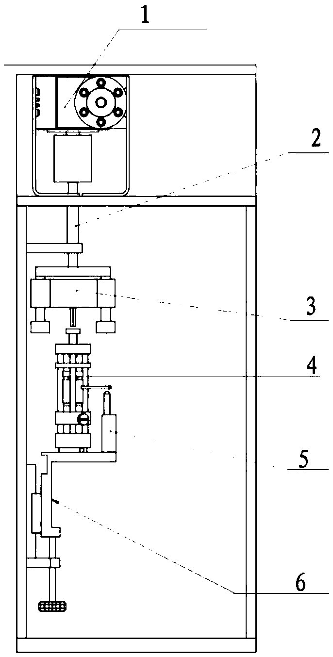
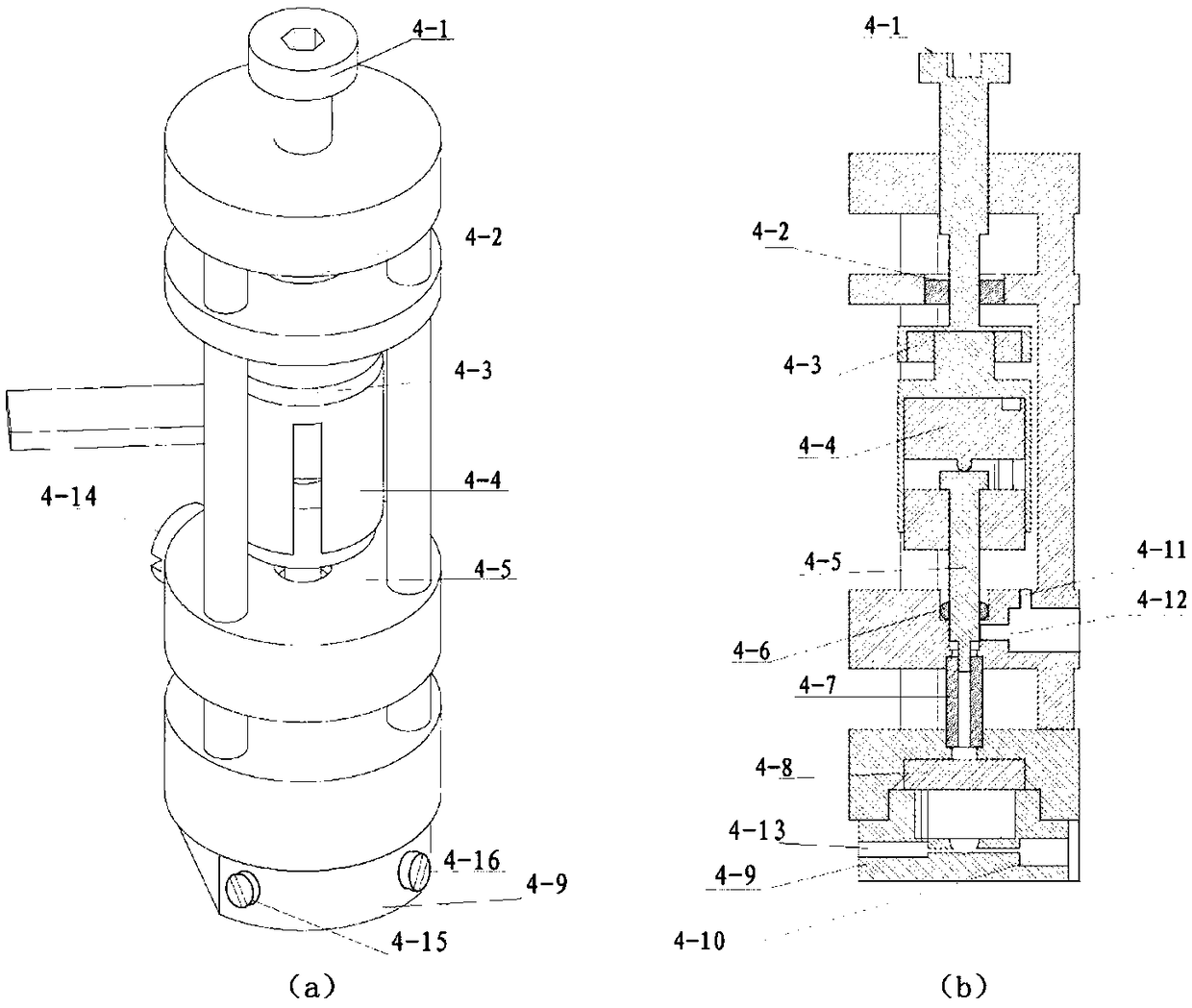
The invention discloses a micro-loess unsaturated suction control loading device and micro-loess unsaturated suction control loading method for a separable pressure chamber. The device comprises a power device, a detachable pressure chamber and a support assembly arranged in order from top to bottom, wherein a soil sample is arranged in the detachable pressure chamber, a support assembly on one side of the detachable pressure chamber is provided with a displacement sensor for measuring vertical displacement of the soil sample, and the power device is disposed above the detachable pressure chamber for providing a rotational driving force to the detachable pressure chamber. The device has the advantages of simple structure, simple operation, miniaturization of the whole structure, and can separate the sample in the unsaturated state from the loading equipment for scanning with high precision CT.

Description

technical field [0001] The invention belongs to the technical field of geotechnical engineering tests, and in particular relates to a miniature loess unsaturated suction control loading device and method for a separable pressure chamber. Background technique [0002] For silty clay represented by loess, its suction and permeability characteristics under unsaturated conditions are the core of seepage problems and strength analysis in the field of geotechnical engineering. The unsaturated permeability coefficient and suction state of the soil are closely related to the soil structure. The porosity of the soil, the combination of particles, and the overhead structure composed of the aggregates formed by the clay particles all have a fundamental impact on the unsaturated permeability characteristics and suction of the soil. Therefore, quantifying the structure of soil is the basis for quantitatively analyzing the unsaturated permeability and mechanical behavior of soil. [000...

Claims


Application Information

Patent Timeline
IPC IPC(8): G01N23/046
CPCG01N23/046G01N2223/03G01N2223/1016
Inventor 于宁宇范文梁敬伟邓龙胜
Owner CHANGAN UNIV
Why Eureka
Eureka Blog
Learn More