Degrees of freedom for diffraction elements in wave expander

A diffraction pattern, light wave technology, used in optical components, instruments, light guides, etc.

Active Publication Date: 2018-12-21
MICROSOFT TECH LICENSING LLC
View PDF5 Cites 8 Cited by
  • Summary
  • Abstract
  • Description
  • Claims
  • Application Information

AI Technical Summary

Problems solved by technology

However, the choice of orientation and period of the diffractive optical element is li

Method used


Image

  • Degrees of freedom for diffraction elements in wave expander
  • Degrees of freedom for diffraction elements in wave expander
  • Degrees of freedom for diffraction elements in wave expander

Examples


Embodiment Construction

[0019] In this specification, reference to "an embodiment," "one embodiment," etc. means that the particular feature, function, structure, or characteristic being described is included in at least one embodiment of the technology presented herein. The appearances of such phrases in this specification are not necessarily all referring to the same embodiment. On the other hand, the further mentioned embodiments are not necessarily mutually exclusive.

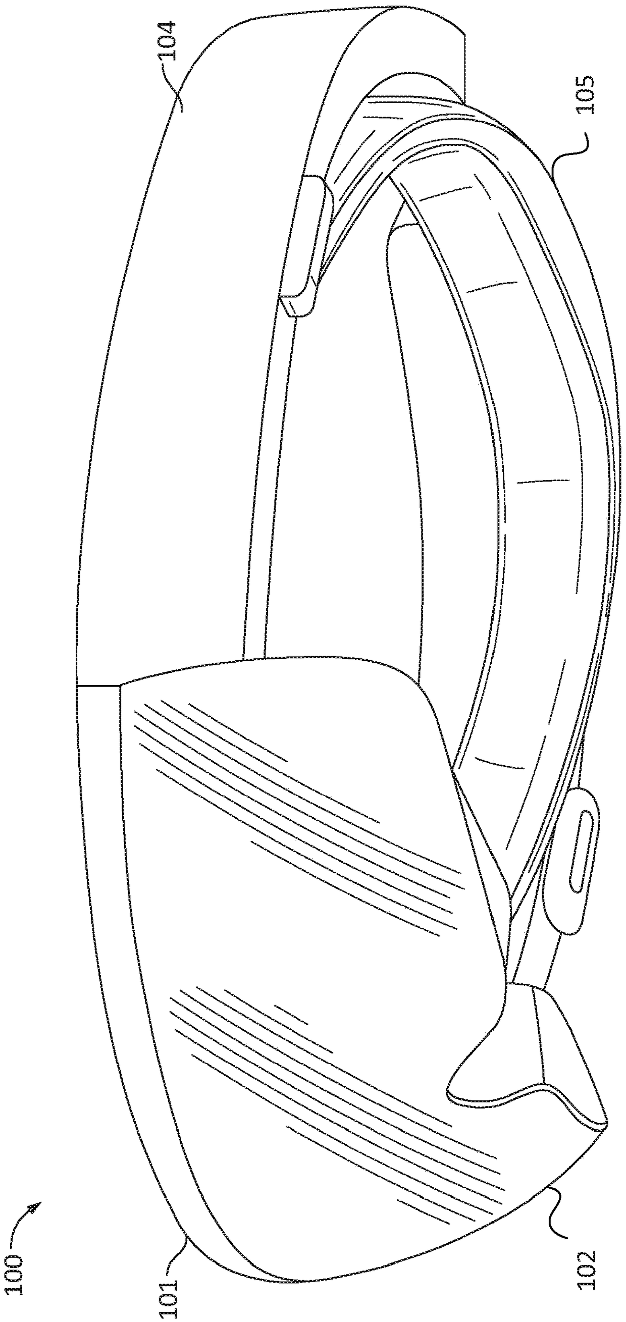
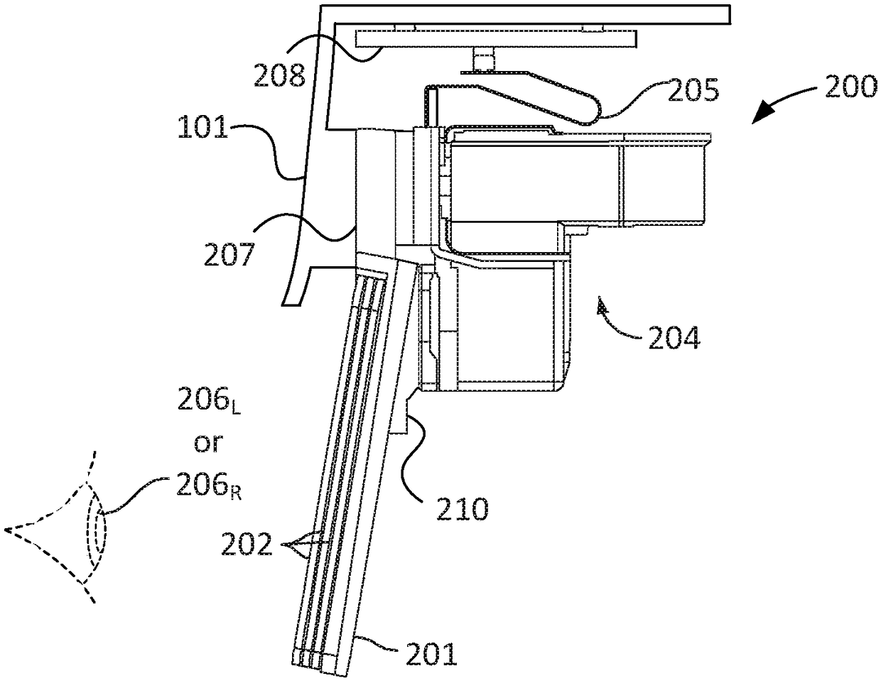
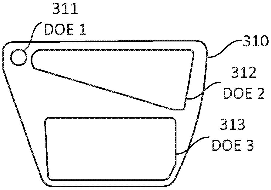
[0020] Some near-eye AR display devices include one or more waveguides positioned in front of one or more light receptors of a user (eg, a human eye). The output waveguide can propagate and expand the light waves provided by the imager and direct the light waves towards the light receptors of the user of the near-eye AR display device using a diffractive optical element (DOE). For example, an output waveguide can spread light waves in a particular direction. Expansion in this context means that a light wave is divided into multi...


PUM


Abstract

Disclosed are an apparatus and method for providing additional degrees of freedom for diffraction gratings of an output waveguide in a near-eye display device. The near-eye display device includes animager to generate an image based on light from a light source. The device further includes a waveguide to input a light wave representing the image received from the imager and to output the light wave representing the image toward an optical receptor of a user. The waveguide includes a plurality of diffractive optical elements (DOEs) in a common light path from an input of the waveguide to an output of the waveguide. The DOEs include a plurality of periodic diffraction patterns. Each of the periodic diffraction patterns is represented by a diffraction pattern vector. The periodic diffractionpatterns are determined such that a vector summation of the diffraction pattern vectors equals zero.

Description

Background technique [0001] Near-eye display (NED) devices, such as head-mounted display (HMD) devices, have recently been introduced into the consumer market to support visualization technologies such as augmented reality (AR) and virtual reality (VR). A near-eye display device may include components such as one or more light sources, a microdisplay module, control electronics, and various optics such as waveguides, lenses, beam splitters, and the like. [0002] Waveguides may be used in near-eye display devices to convey light representing an artificially generated image from the device's image-generating components to a user's light receptor (eg, the human eye). One or more of these waveguides may serve as the image output interface of the user's device; these waveguides may be referred to as the "output waveguides" of the device. For example, with a near-eye AR device, a user can see a computer-generated image projected from a transparent output waveguide through which th...

Claims


Application Information

Patent Timeline
IPC IPC(8): G02B27/00G02B27/01
CPCG02B27/0081G02B2027/0174G02B2027/0123G02B27/0172G02B6/124G02B27/4211G02B27/4272G02B2027/0116
Inventor J·K·T·特沃
Owner MICROSOFT TECH LICENSING LLC
Why Eureka
Try Eureka