Camera, camera shooting device and drone

A camera and mounting hole technology, applied in image communication, television, cooling/ventilation/heating transformation, etc., can solve the problems of high space requirements, high cost, complex structure, etc., and achieve small space requirements, low cost, and simple structure Effect

Inactive Publication Date: 2018-12-21
SZ DJI TECH CO LTD
View PDF10 Cites 1 Cited by
  • Summary
  • Abstract
  • Description
  • Claims
  • Application Information

AI Technical Summary

Problems solved by technology

However, the above-mentioned existing heat dissipation design for cameras requires high space, complex structure and high cost

Method used


Image

  • Camera, camera shooting device and drone
  • Camera, camera shooting device and drone
  • Camera, camera shooting device and drone

Examples


Embodiment approach

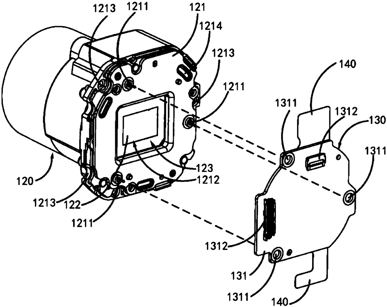
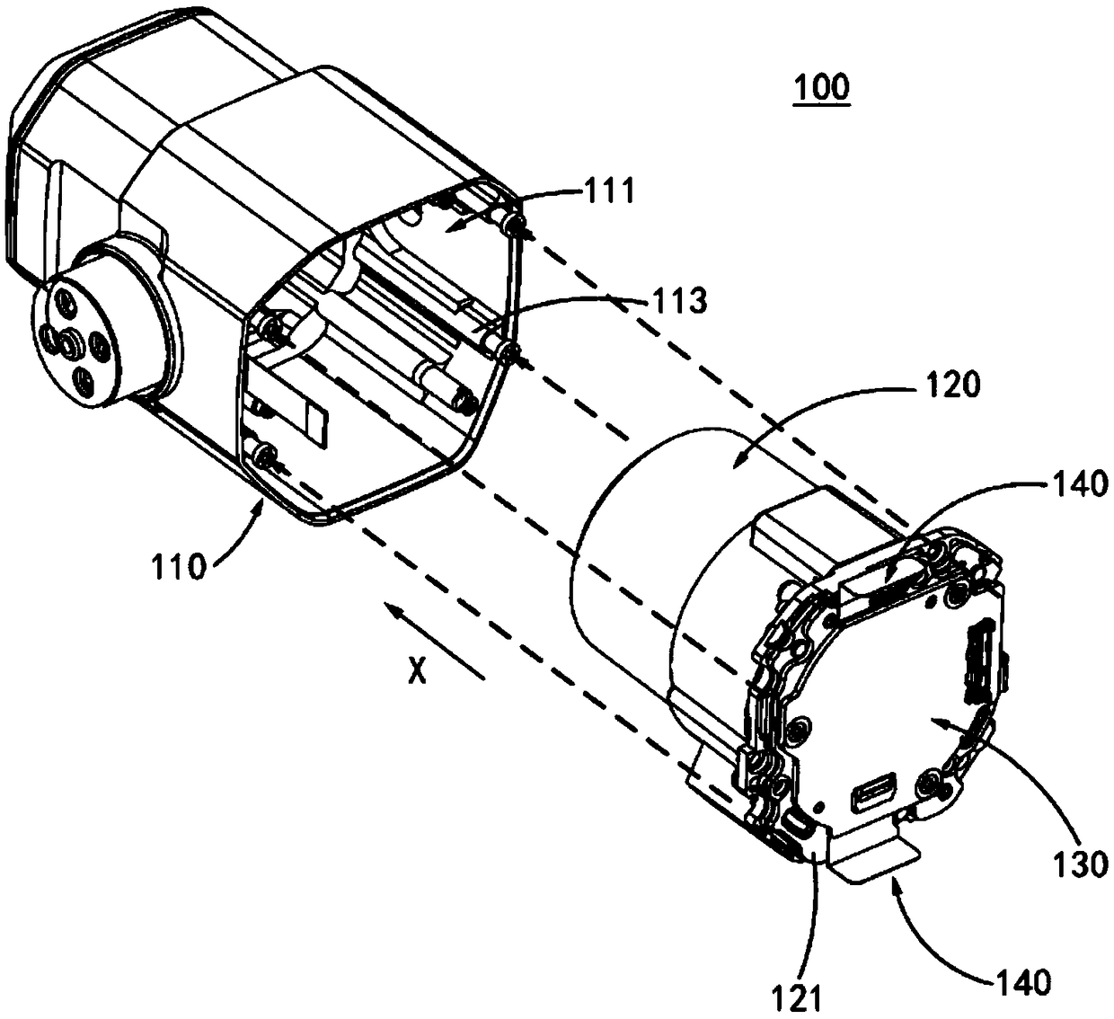
[0058] refer to figure 1 , figure 1 Fig. 1 shows a representative schematic diagram of a partial structure of a camera capable of embodying the principle of the present invention, and specifically shows a schematic diagram of an assembly of a lens assembly and a sensor module of the camera. In this exemplary embodiment, the camera proposed by the present invention is applied to a camera device with a pan-tilt or an unmanned aerial vehicle with a pan-tilt axis as an example for illustration. Those skilled in the art can easily understand that, in order to apply the relevant design of the camera to other types of camera devices or drones, various modifications, additions, substitutions, deletions or other modifications are made to the following specific embodiments variations, which are still within the scope of the principles of the camera proposed by the present invention.

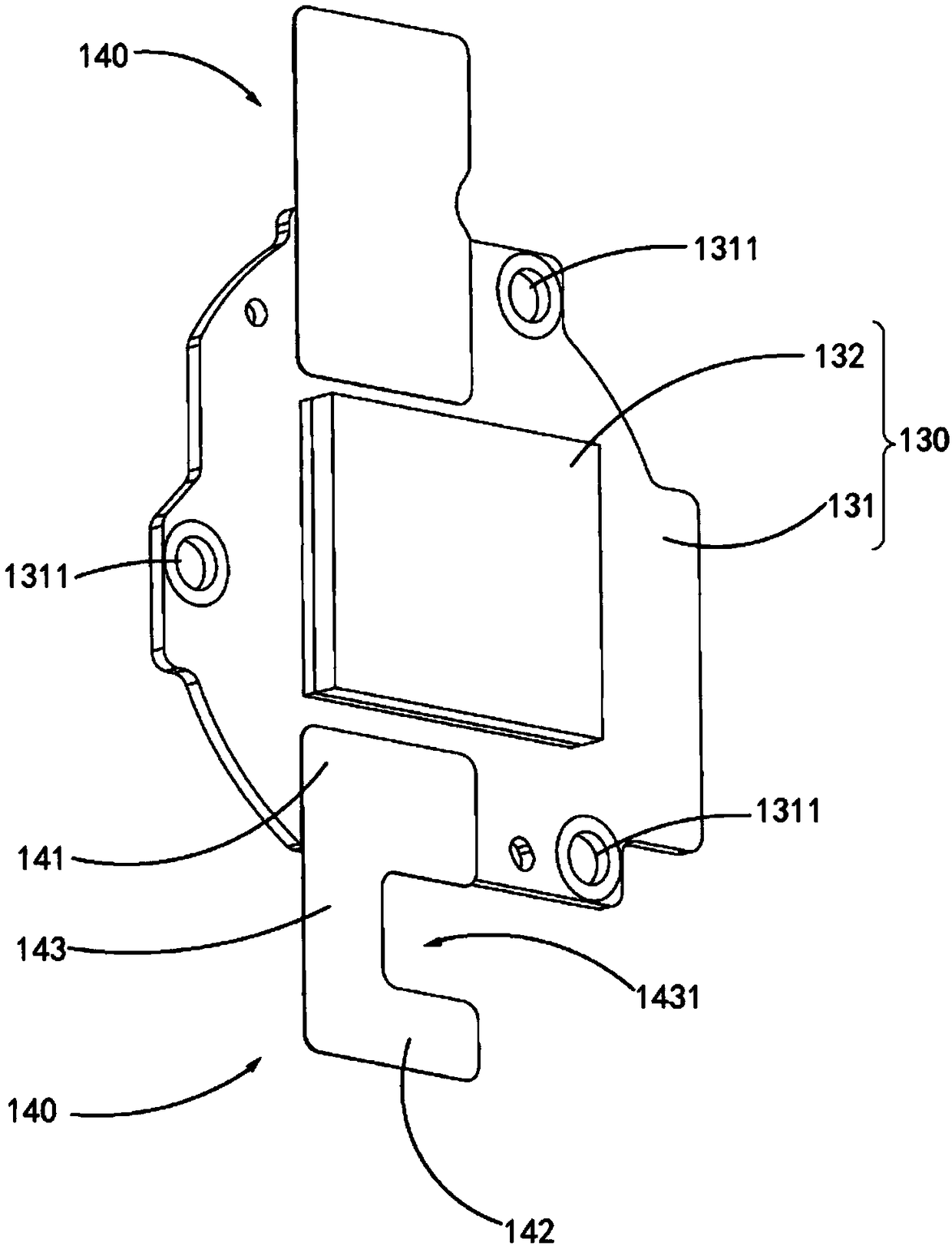
[0059] Such as figure 1 shown, and refer to figure 2 with image 3 , in this embodiment, the came...


PUM


Abstract

The invention discloses a camera (100), a camera shooting device and a drone. The camera (100) includes a housing (110), a lens assembly (120), a sensor module (130), and at least one heat radiating fin (140). The lens assembly (120) is disposed inside the outer casing (110). The sensor module (130) is disposed inside the outer casing (110) and disposed at the rear end of the lens assembly (120).The sensor module (130) includes a circuit board (131) and an imaging sensor (132). The imaging sensor (132) is disposed on a front surface of the circuit board (131) facing the lens assembly (120). The heat radiating fin (140) includes a first end (141) and a second end (142) away from the first end (141). The first end (141) is connected to the circuit board (131) and the second end (142) abutsagainst the inner wall of the outer casing (110) such that heat of the sensor module (130) is transferred to the outer casing (110) via the heat sink (140).

Description

technical field [0001] The present invention relates to the technical field of imaging equipment, in particular, to a camera, an imaging device and an unmanned aerial vehicle. Background technique [0002] Existing cameras generally adopt a heat dissipation design in which the heat source and the housing are connected through structural components for heat conduction. For example, a heat pipe is arranged between the heat source of the camera and the casing, or a fan is used to enhance air convection in the camera to achieve heat dissipation. However, the above-mentioned existing heat dissipation design for cameras requires high space, complex structure and high cost. Contents of the invention [0003] The technical problem to be solved by the present invention is how to provide a heat dissipation design for a camera with low space requirement, simple structure and low cost. [0004] Additional aspects and advantages of the invention will be set forth in the description w...

Claims


Application Information

Patent Timeline
Patent Type & Authority Applications(China)
IPC IPC(8): H05K7/20H04N5/225
CPCH05K7/20445H04N23/50
Inventor 王平
Owner SZ DJI TECH CO LTD
Why Eureka
Try Eureka