Optical cold machining equipment for microscope production

A microscope and optical technology, applied in metal processing equipment, grinding/polishing equipment, optical surface grinder, etc., can solve the problems of unable to automatically control the flow rate of coolant, unable to automatically dry the microscope, unable to realize automatic grinding, etc., to achieve Cooling effect, heat reduction effect

Active Publication Date: 2021-04-27
上饶市鑫锐光电有限公司
View PDF11 Cites 0 Cited by
  • Summary
  • Abstract
  • Description
  • Claims
  • Application Information

AI Technical Summary

Problems solved by technology

[0005] In order to overcome the shortcomings of traditional microscope polishing equipment that cannot realize automatic grinding, automatic control of cooling liquid flow rate and automatic drying of microscope, the technical problem of the present invention is to provide a microscope that can realize automatic grinding, automatic control of cooling liquid flow rate and automatic drying microscope Optical cold processing equipment for microscope production

Method used


Image

  • Optical cold machining equipment for microscope production
  • Optical cold machining equipment for microscope production
  • Optical cold machining equipment for microscope production

Examples


Embodiment 1

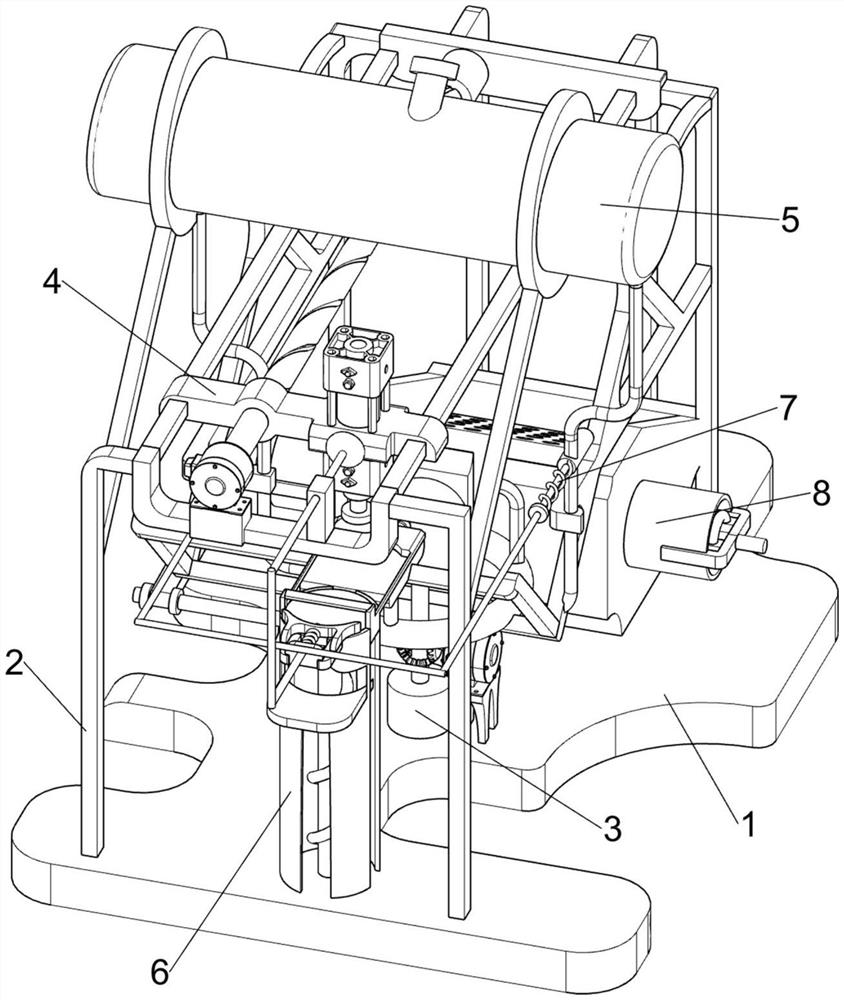
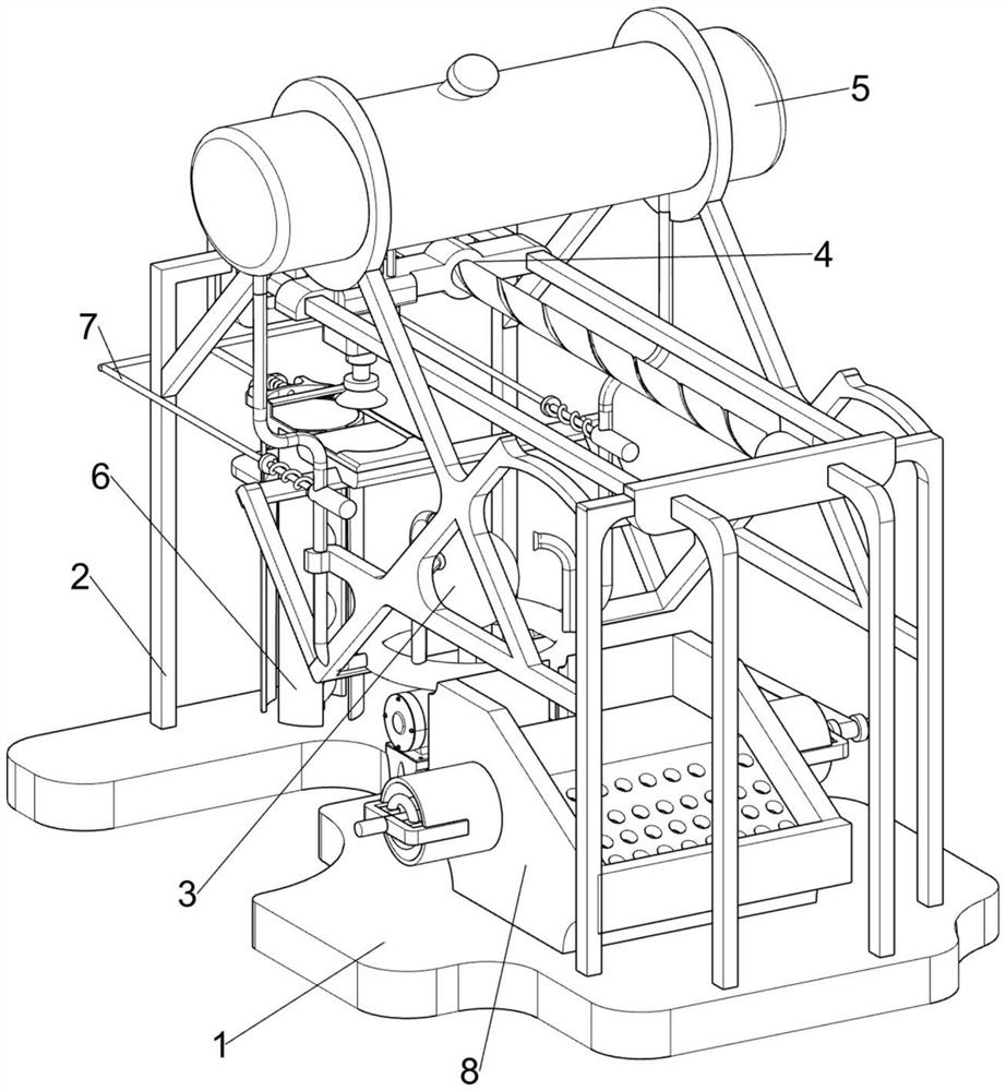
[0066] An optical cold processing equipment for microscope production, such as figure 1 and figure 2 As shown, base plate 1, support 2, grinding mechanism 3 and delivery mechanism 4 are included, base plate 1 is provided with support 2, base plate 1 upper middle part is provided with grinding mechanism 3, and support 2 top is provided with delivery mechanism 4.

[0067] When people want to polish the microscope, they can use this kind of optical cold processing equipment for microscope production. First, the user places the microscope on the base plate 1, then starts the grinding mechanism 3 and the transport mechanism 4, and the transport mechanism 4 is on the base plate 1. The microscope is adsorbed. After the adsorption of the microscope is completed, the transport mechanism 4 transports the microscope to the top of the polishing mechanism 3. The user controls the transport mechanism 4 to move downward, so that the transport mechanism 4 drives the microscope to move downwa...

Embodiment 2

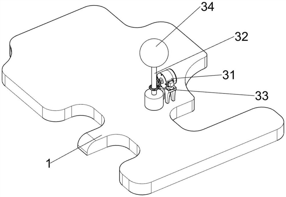
[0069] On the basis of Example 1, such as image 3 and Figure 4 As shown, the grinding mechanism 3 includes a first servo motor 31, a first rotating shaft 32, a bevel gear set 33 and a circular friction wheel 34. The right side of the base plate 1 is equipped with the first servo motor 31. There is a first rotating shaft 32, a bevel gear set 33 is connected between the output shaft of the first servo motor 31 and the first rotating shaft 32, and a circular friction wheel 34 is arranged on the top of the first rotating shaft 32.

[0070] When the user wants to polish the microscope, the user starts the first servo motor 31, the output shaft of the first servo motor 31 drives the bevel gear set 33 to rotate, the bevel gear set 33 drives the first rotating shaft 32 to rotate, and the first rotating shaft 32 drives The circular friction wheel 34 rotates, and the user manually places the microscope on the circular friction wheel 34, and the circular friction wheel 34 polishes the...

Embodiment 3

[0074] On the basis of Example 2, such as Figure 5-Figure 8 As shown, a cooling mechanism 5 is also included. The cooling mechanism 5 includes a liquid storage tank 51, a liquid guide tube 52 and an atomizing nozzle 53. The top of the support 2 is provided with a liquid storage tank 51, and the bottom of the liquid storage tank 51 is provided with a liquid guide tube 52, the catheter 52 is connected to the bracket 2, and the catheter 52 is provided with three atomizing nozzles 53.

[0075] During the grinding process of the microscope, heat will be generated, which will cause certain damage to the microscope and the circular friction wheel 34. In order to avoid this kind of situation, when the microscope is being polished, the user injects cooling liquid into the liquid storage tank 51 to cool down. The liquid flows into the liquid guide pipe 52 through the liquid storage tank 51, and the cooling liquid flows into the atomizing nozzle 53 from the liquid conducting pipe 52, an...


PUM


Abstract

The invention relates to cold machining equipment, in particular to optical cold machining equipment for microscope production. The invention provides the optical cold machining equipment for microscope production which can realize automatic grinding, automatic control over the flow speed of cooling liquid and automatic microscope drying. The optical cold machining equipment for microscope production comprises a bottom plate, a grinding mechanism, and a conveying mechanism; a support is arranged on the bottom plate; the grinding mechanism is arranged in the middle on the bottom plate; and the conveying mechanism is arranged on the upper portion of the support. According to the invention, the microscope is manually placed on a circular friction wheel, the circular friction wheel polishes the microscope, and the effect that the circular friction wheel polishes the microscope is achieved; and a lead screw drives a moving block to move forwards, and the moving block drives an air cylinder, a suction cup and the polished microscope to move forwards to return to the original position, so that the moving block conveying effect is achieved.

Description

technical field [0001] The invention relates to a cold processing equipment, in particular to an optical cold processing equipment for microscope production. Background technique [0002] A microscope is an optical instrument composed of a lens or a combination of several lenses. It is a sign that human beings have entered the atomic age. It is mainly used to magnify tiny objects and become instruments that can be seen by human eyes. Microscopes, optical microscopes and electron microscopes . [0003] The patent application CN208178852U, with a publication date of 20181204, discloses a turntable steel ball automatic installation equipment for microscopes, including a workbench, a bead hole, a cylinder, a needle cylinder, a limit plate, a fixed sleeve, a slider, a lifting rod and Rubber shell, etc., by placing the microscope on the workbench, the user puts the steel ball into the bead hole, the steel ball enters the needle barrel through the bead hole, starts the cylinder, a...

Claims


Application Information

Patent Timeline
Patent Type & Authority Applications(China)
IPC IPC(8): B24B13/00B24B55/03
CPCB24B13/00B24B55/03
Inventor 刘申
Owner 上饶市鑫锐光电有限公司
Why Eureka
Try Eureka