Optical cold processing equipment for microscope production
A microscope and optical technology, applied in the direction of metal processing equipment, grinding/polishing equipment, optical surface grinder, etc., can solve the problems of unable to automatically control the flow rate of coolant, unable to automatically dry the microscope, unable to realize automatic grinding, etc., to reduce Heat, to achieve the effect of cooling effect
- Summary
- Abstract
- Description
- Claims
- Application Information
AI Technical Summary
Problems solved by technology
Method used
Image
Examples
Embodiment 1
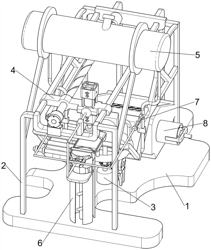
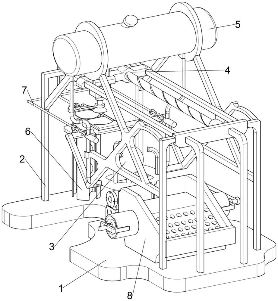
[0066] An optical cold working equipment for microscope production, such as figure 1 and figure 2 As shown, it includes a bottom plate 1, a bracket 2, a grinding mechanism 3 and a conveying mechanism 4. The bottom plate 1 is provided with a bracket 2, the upper middle of the bottom plate 1 is provided with a grinding mechanism 3, and the upper portion of the bracket 2 is provided with a transport mechanism 4.
[0067] When people want to grind the microscope, this optical cold working equipment for microscope production can be used. First, the user places the microscope on the base plate 1, and then starts the grinding mechanism 3 and the transport mechanism 4, and the transport mechanism 4 is placed on the base plate 1. After the adsorption of the microscope is completed, the transport mechanism 4 transports the microscope to the top of the grinding mechanism 3, and the user controls the transport mechanism 4 to move downward, so that the transport mechanism 4 drives the mic...
Embodiment 2
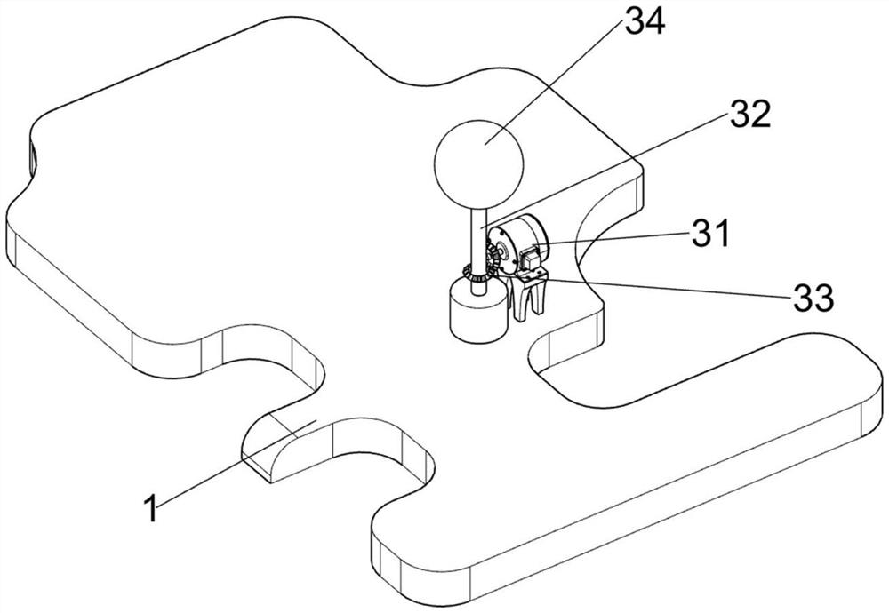
[0069] On the basis of Example 1, as image 3 and Figure 4 As shown, the grinding mechanism 3 includes a first servo motor 31, a first rotating shaft 32, a bevel gear set 33 and a circular friction wheel 34, a first servo motor 31 is installed on the right side of the bottom plate 1, and a rotary There is a first rotating shaft 32 , a bevel gear set 33 is connected between the output shaft of the first servo motor 31 and the first rotating shaft 32 , and a circular friction wheel 34 is provided on the upper part of the first rotating shaft 32 .
[0070] When the user wants to polish the microscope, the user activates the first servo motor 31, the output shaft of the first servo motor 31 drives the bevel gear set 33 to rotate, the bevel gear set 33 drives the first rotating shaft 32 to rotate, and the first rotating shaft 32 drives The circular friction wheel 34 rotates, the user manually places the microscope on the circular friction wheel 34, and the circular friction wheel...
Embodiment 3
[0074] On the basis of Example 2, as Figure 5-Figure 8 As shown, it also includes a cooling mechanism 5, the cooling mechanism 5 includes a liquid storage tank 51, a liquid conduit 52 and an atomizing nozzle 53, the upper part of the bracket 2 is provided with a liquid storage tank 51, and the bottom of the liquid storage tank 51 is provided with a liquid conduit pipe 52 , the catheter 52 is connected to the bracket 2 , and three atomizing nozzles 53 are arranged on the catheter 52 .
[0075] During the grinding process of the microscope, heat will be generated, which will cause certain damage to the microscope and the circular friction wheel 34. In order to avoid such a situation, the user injects coolant into the liquid storage tank 51 when grinding the microscope to cool it down. The liquid flows into the liquid conduit 52 through the liquid storage tank 51, and the cooling liquid flows from the liquid conduit 52 into the atomizing nozzle 53, and finally sprays out from th...
PUM
 Abstract
Description
Claims
Application Information
 - R&D
- Intellectual Property
- Life Sciences
- Materials
- Tech Scout
- Unparalleled Data Quality
- Higher Quality Content
- 60% Fewer Hallucinations
Browse by: Latest US Patents, China's latest patents, Technical Efficacy Thesaurus, Application Domain, Technology Topic, Popular Technical Reports.
© 2025 PatSnap. All rights reserved.Legal|Privacy policy|Modern Slavery Act Transparency Statement|Sitemap|About US| Contact US: help@patsnap.com


