Screw detection method and device

A detection method and screw technology, which is applied in the field of industrial manufacturing, can solve the problems of low screw detection efficiency and the inability of non-indexing disc screw detection machines to accurately control screw detection, and achieve the effect of improving detection efficiency

Active Publication Date: 2018-12-28
ZHUHAI GREE INTELLIGENT EQUIP CO LTD +1
View PDF7 Cites 2 Cited by
  • Summary
  • Abstract
  • Description
  • Claims
  • Application Information

AI Technical Summary

Problems solved by technology

[0005] The embodiment of the present invention provides a screw detection method and device to at least solve the technical problem of low screw detection efficiency due to the inability of the non-indexing disc screw detection machine to accurately control the screw for detection

Method used


Image

  • Screw detection method and device
  • Screw detection method and device
  • Screw detection method and device

Examples


Embodiment 1

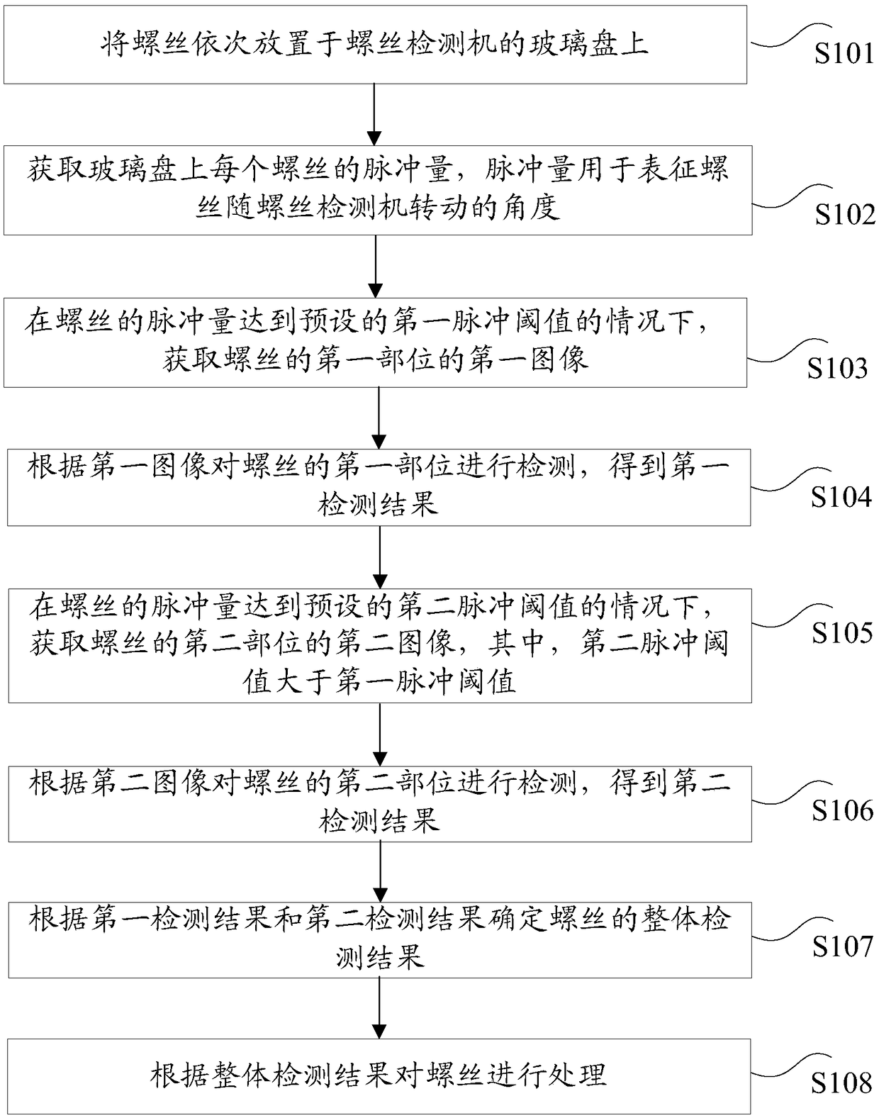
[0025] According to an embodiment of the present invention, a screw detection method is provided, which is applied to a screw detection machine, such as figure 1 As shown, the method includes:

[0026] S101, placing the screws on the glass plate of the screw detection machine in sequence;

[0027] S102, acquiring the pulse amount of each screw on the glass plate, the pulse amount is used to represent the angle at which the screw rotates with the screw detector;

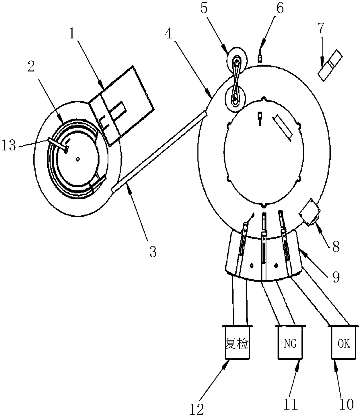
[0028] In the related art, the precise control of the screw cannot be realized for the non-dividing disc screw detection machine. Therefore, in the embodiment of the present invention, a screw detection method is proposed to realize the non-dividing disc screw detection. The screw can be precisely controlled in the machine. For example, if figure 2 As shown in the non-indexing disk detector, there is a sensor 6 in the non-indexing disk detector, and the screw is fed into the optical glass disk of the non-grading d...

Embodiment 2

[0073] According to an embodiment of the present invention, a screw detection device for implementing the above screw detection method is also provided, such as Figure 4 As shown, the device includes:

[0074] 1) The distributing unit 401 is used to place the screws sequentially on the glass plate of the screw inspection machine;

[0075] 2) The first acquisition unit 402 is used to acquire the pulse amount of each screw on the glass plate, and the pulse amount is used to represent the angle at which the screw rotates with the screw detector;

[0076] 3) A second acquisition unit 403, configured to acquire a first image of a first part of the screw when the pulse amount of the screw reaches a preset first pulse threshold;

[0077] 4) a first detection unit 404, configured to detect the first part of the screw according to the first image, and obtain a first detection result;

[0078] 5) A third acquisition unit 405, configured to acquire a second image of a second part of t...

Embodiment 3

[0088] According to an embodiment of the present invention, a storage medium is further provided, and the storage medium includes a stored program, wherein the above screw detection method is executed when the program is running.

[0089] Optionally, in this embodiment, the storage medium is configured to store program codes for performing the following steps:

[0090] S1, place the screws on the glass plate of the screw detector in sequence;

[0091] S2. Obtain the pulse amount of each screw on the glass plate, the pulse amount is used to represent the angle at which the screw rotates with the screw detector;

[0092] S3. Acquire a first image of a first part of the screw when the pulse amount of the screw reaches a preset first pulse threshold;

[0093] S4. Detect the first part of the screw according to the first image, and obtain a first detection result;

[0094] S5. Acquire a second image of a second part of the screw when the pulse amount of the screw reaches a preset...


PUM


Abstract

The invention discloses a screw detection method and device. The method comprises the steps that screws are placed on glass discs of a screw detector in sequence, and the pulse quantity of each screwon the glass disc is obtained; a first image of the first part of the screw is obtained under the condition that the pulse quantity of the screw reaches a preset first pulse threshold value; the firstpart of the screw is detected according to the first image to obtain a first detection result; a second image of the second part of the screw is obtained under the condition that the pulse quantity of the screw reaches a preset second pulse threshold value; the second part of the screw is detected according to the second image to obtain a second detection result; and the integral detection resultof the screw is determined according to the first detection result and the second detection result, and the screw is processed according to the integrated detection result. By virtue of the method, the problem of relatively low screw detection efficiency caused by the fact that the screw cannot be accurately controlled by a non-graduated disk type screw detector for detection is solved.

Description

technical field [0001] The invention relates to the field of industrial manufacturing, in particular to a screw detection method and device. Background technique [0002] The non-indexing disc screw inspection machine uses a vibrating disc to transport the screws to the optical glass disc in a non-fixed way with the nut facing down and the screw rod facing up (the speed is about 300 pieces / min). The optical glass disc rotates, and when the screw is rotated to the detection area of ​​the side or front optical detection mechanism, the camera is triggered to take pictures, and the detection result is obtained after computer processing. Then, the optical glass disc continues to rotate, and the screw is rotated to the lower level of good quality OK or poor quality NG. According to the judgment result of the optical detection system, the distributor blows the screw to the OK product outlet or the NG product outlet. Because the screw is not fixed in the specified position of the ...

Claims


Application Information

Patent Timeline
Patent Type & Authority Applications(China)
IPC IPC(8): B07C5/34B07C5/02B07C5/36
CPCB07C5/02B07C5/34B07C5/365
Inventor 黄永建邓及翔张天翼
Owner ZHUHAI GREE INTELLIGENT EQUIP CO LTD
Why Eureka
Try Eureka