Nut demounting tool for metallurgical mechanical equipment

A technology for mechanical equipment and nuts, applied in the field of metallurgical machinery and equipment nut disassembly and assembly tools, can solve the problems of large volume, increased disassembly and assembly time, inconvenient disassembly and assembly of nuts, etc., and achieves the effect of simple operation, convenient adjustment, and labor-saving disassembly and assembly.

Active Publication Date: 2018-12-28
曾美霞
View PDF8 Cites 3 Cited by
  • Summary
  • Abstract
  • Description
  • Claims
  • Application Information

AI Technical Summary

Problems solved by technology

[0002] Metallurgical machinery and equipment are generally large in size and heavy in weight, and the connecting bolts used are also relatively large. Due to the needs of equipment design, the nuts of many connecting bolts have different shapes and sizes, and most of them use hexagonal nuts; the existing metallurgical machinery When the equipment nut removal tool is in use, it can only disassemble a single nut. If you need to disassemble nuts of different specifications, you need to use different disassembly tools. Therefore, you need to find suitable tools for disassembly. It not only increases the workload of the staff, but also increases the disassembly and assembly time, which makes the disassembly and assembly of nuts very inconvenient; at the same time, when disassembling and assembling various nuts of existing metallurgical machinery and equipment, most of them are disassembled and assembled by hand using a wrench , and due to the large metallurgical machinery and equipment, the nuts are very firm when installed, and because the wrench is too short, it is a great challenge to human physical strength when disassembling the nuts; therefore, it is necessary to design a Metallurgical machinery and equipment nut removal tool to solve the shortage of existing disassembly tools, so as to meet people's needs

Method used


Image

  • Nut demounting tool for metallurgical mechanical equipment
  • Nut demounting tool for metallurgical mechanical equipment
  • Nut demounting tool for metallurgical mechanical equipment

Examples


Embodiment Construction

[0030] The following will clearly and completely describe the technical solutions in the embodiments of the present invention with reference to the accompanying drawings in the embodiments of the present invention. Obviously, the described embodiments are only some, not all, embodiments of the present invention. Based on the embodiments of the present invention, all other embodiments obtained by persons of ordinary skill in the art without making creative efforts belong to the protection scope of the present invention.

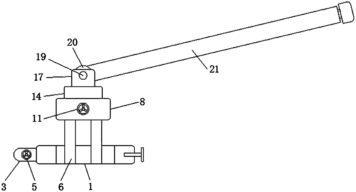
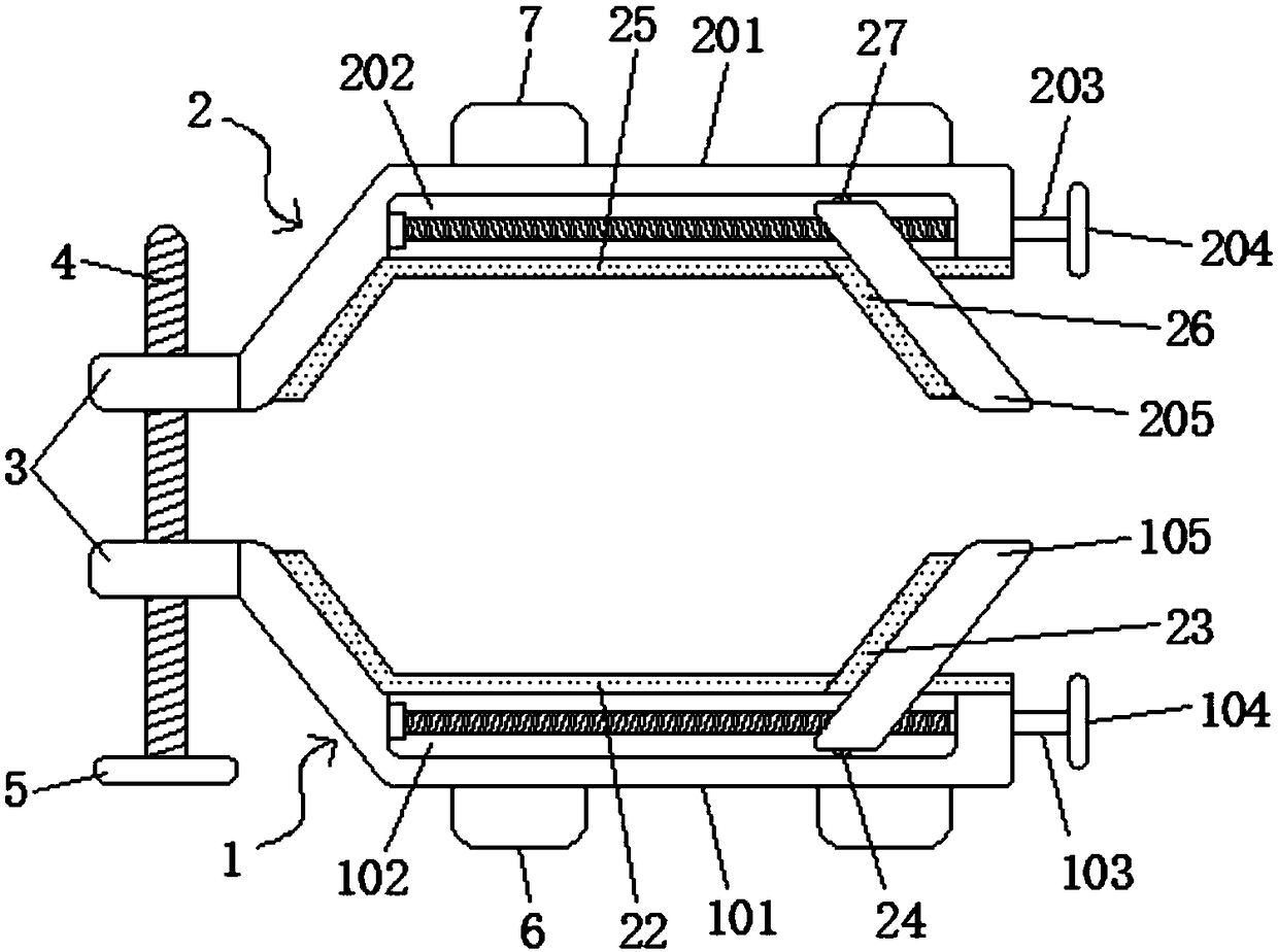
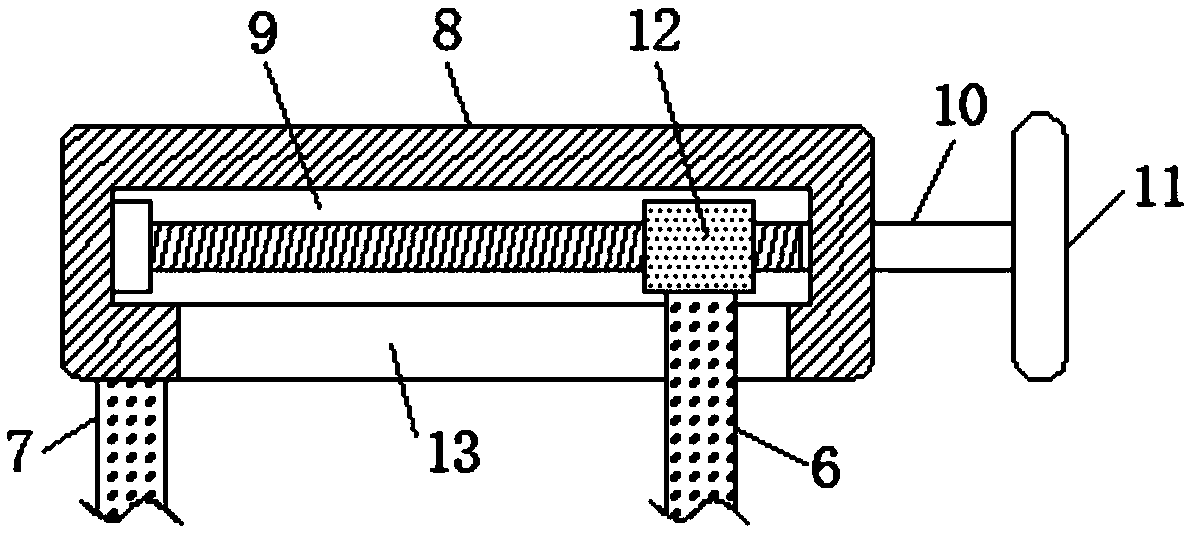
[0031] like Figure 1-7 As shown, the present invention provides a technical solution: a nut removal tool for metallurgical machinery and equipment, including a first clamping and fixing mechanism 1 and a second clamping and fixing mechanism 2 located on the side of the first clamping and fixing mechanism 1, the second clamping and fixing mechanism 2 The left sides of the first clamping and fixing mechanism 1 and the second clamping and fixing mechanism 2 are fi...


PUM


Abstract

The invention discloses a nut demounting tool for metallurgical mechanical equipment. The nut demounting tool comprises a first clamping and fixing mechanism and a second clamping and fixing mechanism. The second clamping and fixing mechanism is located on one side of the first clamping and fixing mechanism, threaded connection fixing blocks are fixedly connected to the left sides of the first clamping and fixing mechanism and the second clamping and fixing mechanism, and a first threaded rod is connected between the threaded connection fixing blocks in a threaded mode. The nut demounting toolhas the advantages that through the first clamping and fixing mechanism, the second clamping and fixing mechanism, a first connection fixing rod, a second connection fixing rod, a connection controlpanel, a connection cylindrical block, a rotating wheel, a fixed connection block, a fixed shaft, a stressed circular block and a rotating rod, the nut demounting tool can demount hex nuts of different specifications; the nuts can be dismounted easily through length adjustment of the rotating rod; the nut demounting tool is convenient to adjust, simple to operate and capable of meeting people's needs.

Description

technical field [0001] The invention relates to the technical field of tools for disassembling metallurgical machinery, in particular to a tool for disassembling nuts of metallurgical machinery. Background technique [0002] Metallurgical machinery and equipment are generally large in size and heavy in weight, and the connecting bolts used are also relatively large. Due to the needs of equipment design, the nuts of many connecting bolts have different shapes and sizes, and most of them use hexagonal nuts; the existing metallurgical machinery When the equipment nut removal tool is in use, it can only disassemble a single nut. If you need to disassemble nuts of different specifications, you need to use different disassembly tools. Therefore, you need to find suitable tools for disassembly. It not only increases the workload of the staff, but also increases the disassembly and assembly time, which makes the disassembly and assembly of nuts very inconvenient; at the same time, w...

Claims


Application Information

Patent Timeline
Patent Type & Authority Applications(China)
IPC IPC(8): B25B27/14
CPCB25B27/14
Inventor 吴帅英
Owner 曾美霞
Why Eureka
Try Eureka