Picture matching method, device, apparatus and storage medium
A matching method and image technology, applied in the field of image processing, can solve the problems of indeterminate position information, low matching accuracy, and low matching accuracy
- Summary
- Abstract
- Description
- Claims
- Application Information
AI Technical Summary
Problems solved by technology
Method used
Image
Examples
Embodiment 1
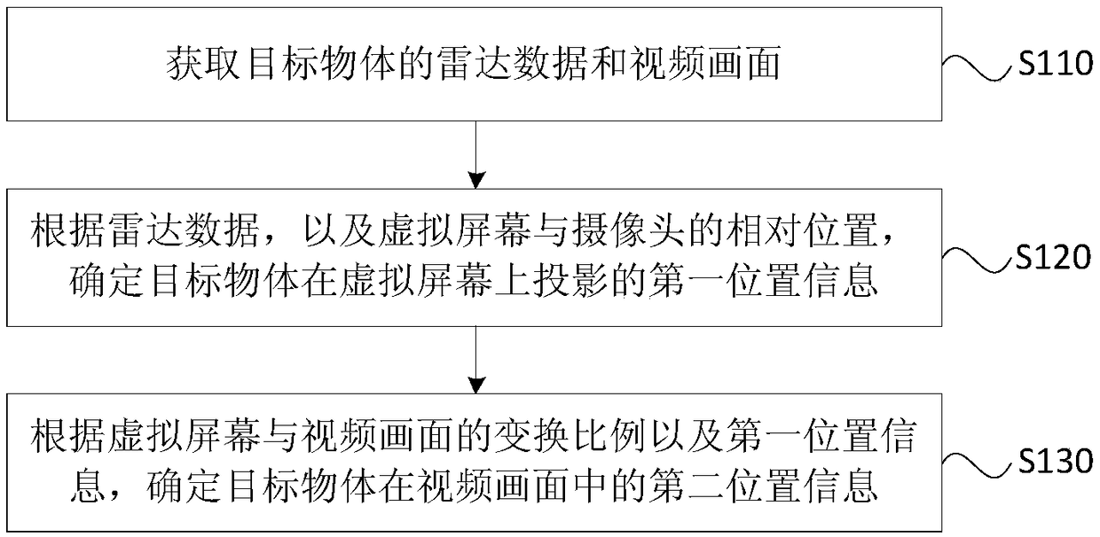
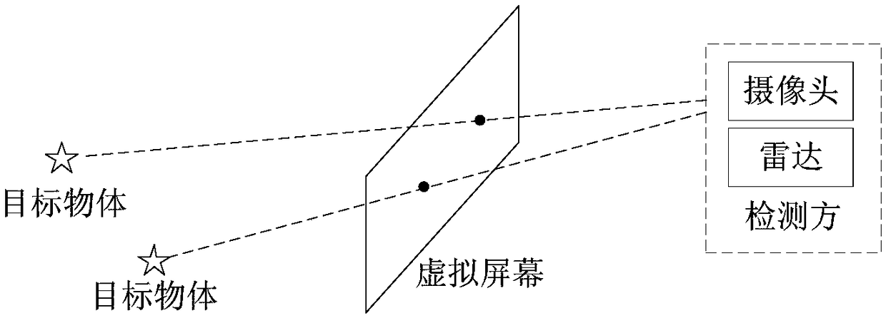
[0034] Figure 1A It is a flow chart of a picture matching method provided by Embodiment 1 of the present invention. This embodiment can be applied to any vehicle equipped with radar and camera, robot, indoor or outdoor fixed monitoring equipment, etc. in the matching case. A screen matching method provided in this embodiment can be executed by a screen matching device provided in an embodiment of the present invention, and the device can be realized by means of software and / or hardware, and integrated into a device that executes this method. In this embodiment In the example, the device for executing the method may be any device capable of performing data background calculations such as a tablet computer, a desktop computer, and a notebook. Specifically, refer to Figure 1A , the method may include the following steps:
[0035] S110, acquiring radar data and video images of the target object.
[0036] Specifically, in this embodiment, in order to visually present the positi...
Embodiment 2
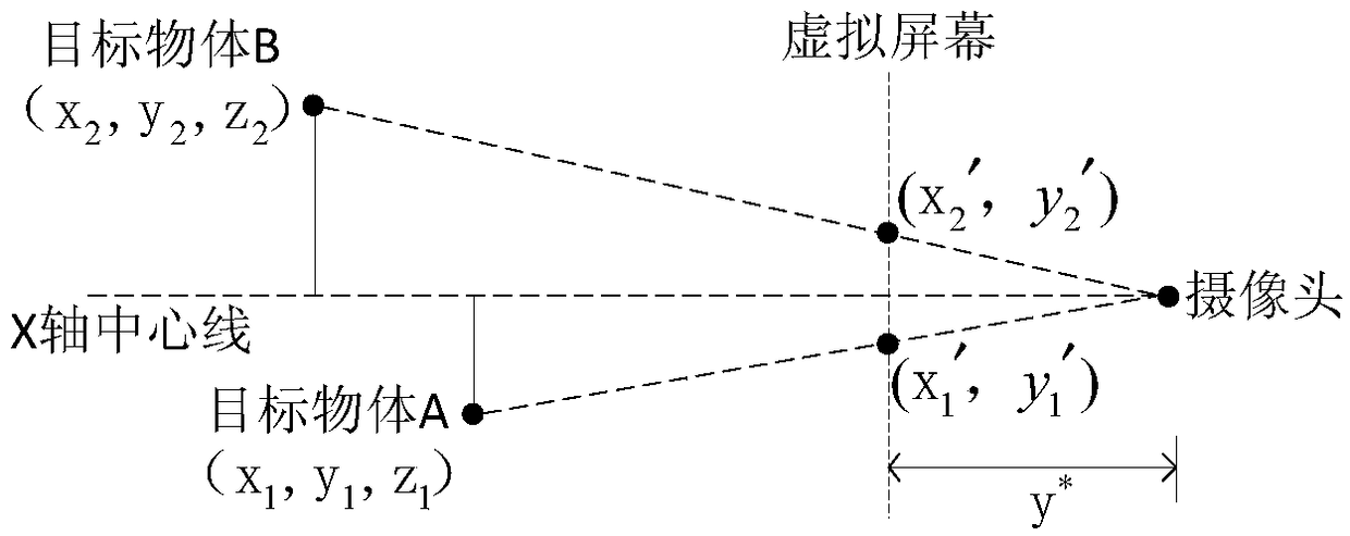
[0053] Figure 2A It is a flow chart of the method for determining the relative position between the virtual screen and the camera in the method provided by Embodiment 2 of the present invention. This embodiment is optimized on the basis of the above-mentioned embodiments. Before performing this method to determine the position of the target object on the video screen, it is necessary to calibrate the relative position of the virtual screen and the camera by setting a corner reflector. Specifically, such as Figure 2A As shown, this embodiment may include the following steps:
[0054] S210. Acquire preset radar reference data and video reference pictures of the corner reflector.
[0055] Wherein, the radar reference data is the actual position data of at least two corner reflectors pre-placed by the user collected by the installed radar when the position of the virtual screen is calibrated. The position of the corner reflector can be determined according to whether the rada...
Embodiment 3
[0066] image 3 It is a flow chart of the method for determining the preset size of the marker frame in the method provided by Embodiment 3 of the present invention. This embodiment is optimized on the basis of the above embodiments. In addition to determining the relative position of the virtual screen and the camera through the corner reflector, it is also possible to predetermine the display position of the corner reflector on the video picture. Dimensions of the corner reflector's marker box. Specifically, such as image 3 As shown, this embodiment may include the following steps:
[0067] S310. Determine the projected size of the marker frame on the virtual screen according to the size and transformation ratio of the marker frame in the video reference frame.
[0068] Wherein, the marker frame is used to mark the corner reflector in the video reference frame, and can also mark the target object in the video frame; at this time, the size of the marker frame in the video...
PUM
 Abstract
Description
Claims
Application Information
 - R&D
- Intellectual Property
- Life Sciences
- Materials
- Tech Scout
- Unparalleled Data Quality
- Higher Quality Content
- 60% Fewer Hallucinations
Browse by: Latest US Patents, China's latest patents, Technical Efficacy Thesaurus, Application Domain, Technology Topic, Popular Technical Reports.
© 2025 PatSnap. All rights reserved.Legal|Privacy policy|Modern Slavery Act Transparency Statement|Sitemap|About US| Contact US: help@patsnap.com


