A picture matching method, device, equipment and storage medium

A picture and reference picture technology, applied in the field of image processing, can solve the problems of indeterminate position information, low matching accuracy, low matching accuracy, etc., and achieve the effect of simplifying the matching process, improving accuracy, and accurate position matching

Active Publication Date: 2021-11-02
CALTERAH SEMICON TECH SHANGHAI CO LTD
View PDF5 Cites 0 Cited by
  • Summary
  • Abstract
  • Description
  • Claims
  • Application Information

AI Technical Summary

Problems solved by technology

[0004] In the prior art, the matching accuracy of manual operation matching is low, and only the approximate position of the target object in the video screen can be obtained, and the specific position information cannot be determined, so the matching accuracy is low

Method used


Image

  • A picture matching method, device, equipment and storage medium
  • A picture matching method, device, equipment and storage medium
  • A picture matching method, device, equipment and storage medium

Examples


Embodiment 1

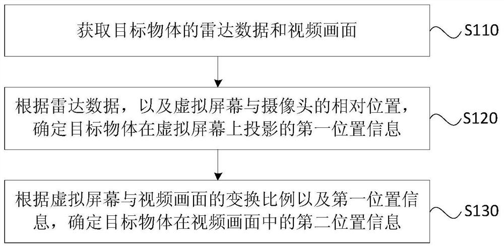
[0034] Figure 1A It is a flow chart of a picture matching method provided by Embodiment 1 of the present invention. This embodiment can be applied to any vehicle equipped with radar and camera, robot, indoor or outdoor fixed monitoring equipment, etc. in the matching case. A picture matching method provided in this embodiment can be executed by a picture matching device provided in an embodiment of the present invention, and the device can be realized by means of software and / or hardware, and integrated into an electronic device that executes the method. The electronic device that executes the method in the embodiment may be any electronic device that can perform data background calculations, such as a tablet computer, a desktop computer, and a notebook. Specifically, refer to Figure 1A , the method may include the following steps:

[0035] S110, acquiring radar data and video images of the target object.

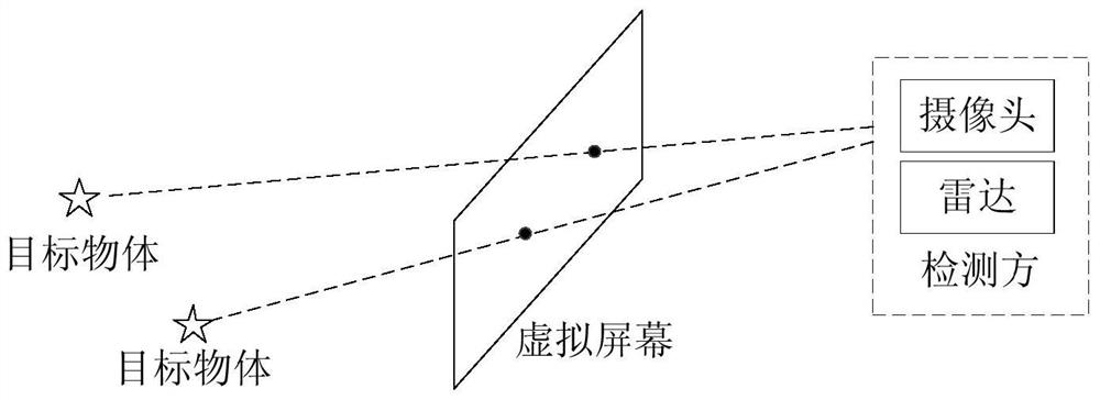
[0036] Specifically, in this embodiment, in order to visually pres...

Embodiment 2

[0053] Figure 2A It is a flow chart of the method for determining the relative position between the virtual screen and the camera in the method provided by Embodiment 2 of the present invention. This embodiment is optimized on the basis of the above-mentioned embodiments. Before performing this method to determine the position of the target object on the video screen, it is necessary to calibrate the relative position of the virtual screen and the camera by setting a corner reflector. Specifically, such as Figure 2A As shown, this embodiment may include the following steps:

[0054] S210. Acquire preset radar reference data and video reference pictures of the corner reflector.

[0055] Wherein, the radar reference data is the actual position data of at least two corner reflectors pre-placed by the user collected by the installed radar when the position of the virtual screen is calibrated. The position of the corner reflector can be determined according to whether the rada...

Embodiment 3

[0066] image 3 It is a flow chart of the method for determining the preset size of the marker frame in the method provided by Embodiment 3 of the present invention. This embodiment is optimized on the basis of the above embodiments. In addition to determining the relative position of the virtual screen and the camera through the corner reflector, it is also possible to predetermine the display position of the corner reflector on the video picture. Dimensions of the corner reflector's marker box. Specifically, such as image 3 As shown, this embodiment may include the following steps:

[0067] S310. Determine the projected size of the marker frame on the virtual screen according to the size and transformation ratio of the marker frame in the video reference frame.

[0068] Wherein, the marker frame is used to mark the corner reflector in the video reference frame, and can also mark the target object in the video frame; at this time, the size of the marker frame in the video...


PUM


Abstract

The embodiment of the invention discloses a picture matching method, device, equipment and storage medium. Wherein, the method includes: acquiring radar data and video images of the target object, the video images being collected by a camera; The projected first position information, the virtual screen is located between the camera and the target object; according to the conversion ratio between the virtual screen and the video picture and the first position information, it is determined that the target object is in the The second position information in the video frame. The technical solution provided by the embodiment of the present invention realizes the accurate position matching of the target object on the video screen, improves the position matching accuracy, and simplifies the matching process.

Description

technical field [0001] The embodiments of the present invention relate to the technical field of image processing, and in particular to a picture matching method, device, device and storage medium. Background technique [0002] With the development of image processing technology, the three-dimensional stereoscopic images in daily life are converted into the two-dimensional images captured by the camera to display the required image information to the user, so that the user can intuitively obtain the position information of the target object in the image. For example, when a vehicle is driving on the road, the camera installed in front of the vehicle can detect the running information of other vehicles in front of the vehicle in real time on the road, and match and mark the position of other vehicles in the video screen of the vehicle. , intuitively displayed to the driver of the vehicle, so that the driver can intuitively determine the driving information of the vehicle on t...

Claims


Application Information

Patent Timeline
Patent Type & Authority Patents(China)
IPC IPC(8): G06T7/70G06T3/00G06K9/00
CPCG06T3/0037G06T7/70G06V20/584
Inventor 陈一宽
Owner CALTERAH SEMICON TECH SHANGHAI CO LTD
Why Eureka
Try Eureka