Optical fingerprint sensor

A light sensor and sensor technology, which is applied in the acquisition/organization of fingerprints/palmprints, instruments, electrical solid-state devices, etc., can solve the problems that light cannot reach and the light sensor 26 cannot receive light.

Inactive Publication Date: 2019-01-04
EGIS TECH
View PDF3 Cites 4 Cited by
  • Summary
  • Abstract
  • Description
  • Claims
  • Application Information

AI Technical Summary

Problems solved by technology

In addition, each photosensor 26 only uses a single collimator 36, so the single collimator 36 must be aligned with the light-transmitting zone Z2 of the light-emitting unit Cell in the panel module 51, so as to avoid the single collimator 36 being blocked by the light-emitting unit. Covered by the non-transmissive zone Z1 of the Cell, the light cannot reach the light sensor 26 below the single collimator 36
Therefore, in the traditional optical fingerprint sensor 1, when the sensing module 11 is combined with the panel module 51, it is necessary to combine the light sensor 26 of the sensing module 11 with the light-transmitting zone Z2 of the light-emitting unit Cell of the panel module 51. alignment, and when making the sensing module 11, the light sensor 26 must also be aligned with the collimator 36, so as to avoid that the single collimator 36 will be covered by the non-light-transmitting area Z1 of the panel module 51, or the light sensor The detector 26 cannot receive the light emitted by the light-emitting unit Cell to the user's finger and reflected back

Method used


Image

  • Optical fingerprint sensor
  • Optical fingerprint sensor
  • Optical fingerprint sensor

Examples


Embodiment Construction

[0036] In order to make the above-mentioned and other objects, features, and advantages of the present invention more obvious and understandable, the preferred embodiments are specifically listed below, together with the accompanying drawings and descriptions, and are described in detail as follows:

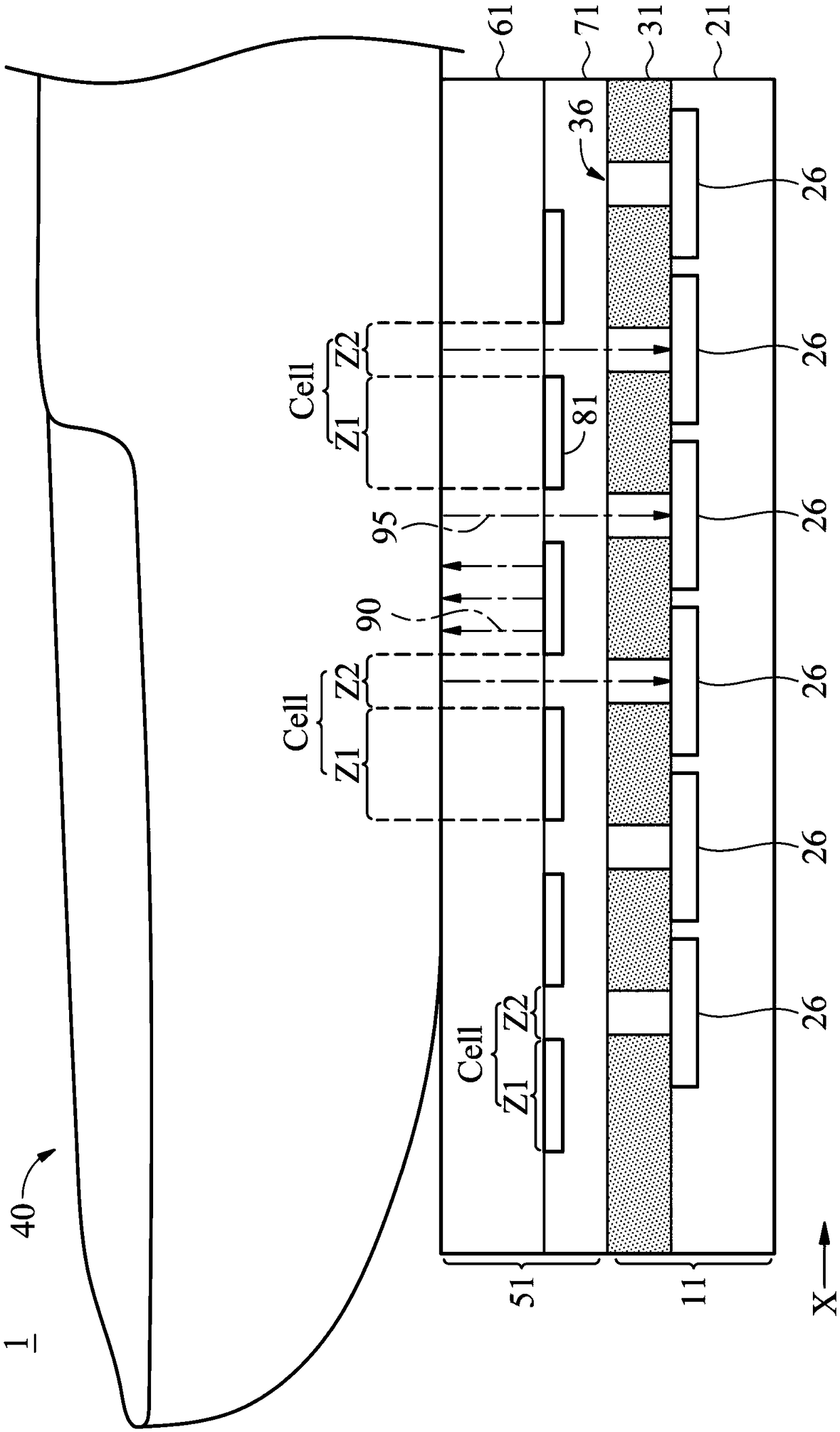
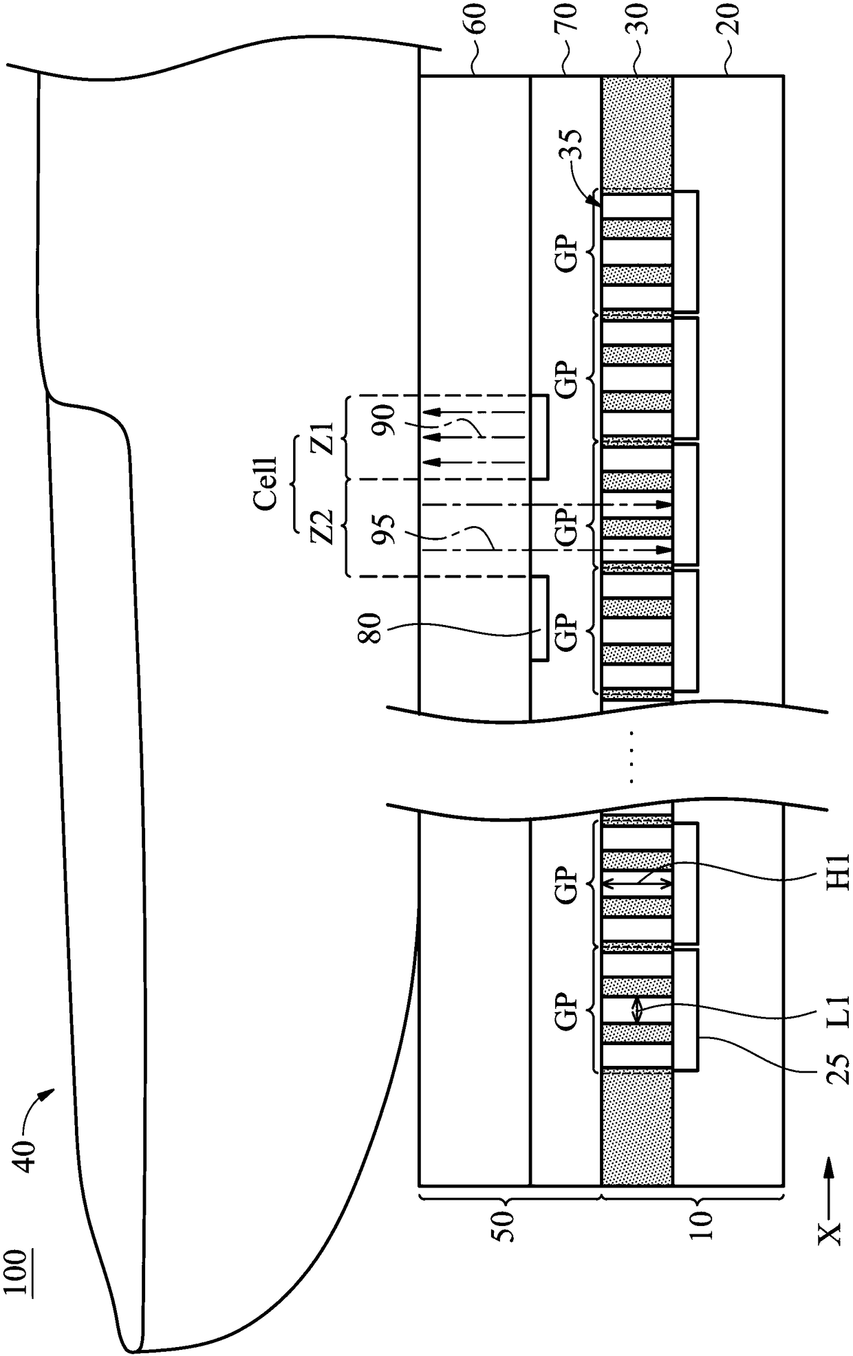
[0037] figure 2 is an optical fingerprint sensor 100 according to some embodiments of the present invention. The optical fingerprint sensor 100 includes a sensing module 10 and a panel module 50 . The sensing module 10 is disposed below the panel module 50 . The optical fingerprint sensor 100 is formed by combining the sensing module 10 and the panel module 50 . In this embodiment, the sensing module 10 is combined with the panel module 50 via an adhesive (not shown).

[0038] The panel module 50 includes a cover glass 60 and a light emitting layer 70 . The light emitting layer 70 includes a light emitting array including a plurality of light emitting units Cell. To simplif...


PUM


Abstract

An optical fingerprint sensor is provided. The optical fingerprint sensor includes a sensing module. The sensing module includes a light sensing layer and a light filter layer disposed above the lightsensing layer. The light sensing layer includes a plurality of photo detectors arranged in a sensing array. The light filter layer includes a plurality of collimators. The collimators are divided into a plurality of collimator groups corresponding to the photo detectors, and the number of collimator groups is equal to the number of photo detectors. Each of the collimator groups comprises the samenumber of collimators arranged in a specific pattern and disposed above the corresponding photo detector. The photo detectors receive reflected light from a user's finger through the collimators of the corresponding collimator groups.

Description

technical field [0001] The present invention relates to an optical fingerprint sensor, and in particular to an optical fingerprint sensor with a specific collimator pattern. Background technique [0002] In recent years, with the gradual maturity of biometric technology, many different biometric features can be used to identify users. Among them, since the recognition rate and accuracy of the fingerprint recognition technology are better than other biometric recognition technologies, the application level of the fingerprint recognition is relatively wide at present. [0003] The technology of fingerprint recognition is to use the sensing device to sense the fingerprint image of the user first, and then obtain the unique fingerprint features in the fingerprint image and store them in the storage memory, or directly store the fingerprint image. Afterwards, when the user presses or swipes the fingerprint again, the fingerprint sensor will sense the fingerprint image and obtain...

Claims


Application Information

Patent Timeline
IPC IPC(8): G06K9/00G06V30/144
CPCG06V40/1318H10K59/65H10K59/8792H01L31/02327H01L27/14623H01L27/14643H01L27/14685H01L31/02164H01L31/167H10K59/60H10K50/865
Inventor 黄郁湘傅同龙范成至
Owner EGIS TECH
Why Eureka
Try Eureka