Transmitting method, receiving method, device, terminal and base station for uplink control channel

A technology for controlling channels and sending methods, which is applied to the separation device of the transmission path, adjustment of channel coding, sub-channel allocation of the transmission path, etc., and can solve problems such as no clear solution

Active Publication Date: 2019-01-04
DATANG MOBILE COMM EQUIP CO LTD
View PDF9 Cites 1 Cited by
  • Summary
  • Abstract
  • Description
  • Claims
  • Application Information

AI Technical Summary

Problems solved by technology

Since the size of the uplink area in different time slots may be different, there

Method used


Image

  • Transmitting method, receiving method, device, terminal and base station for uplink control channel
  • Transmitting method, receiving method, device, terminal and base station for uplink control channel
  • Transmitting method, receiving method, device, terminal and base station for uplink control channel

Examples


Embodiment Construction

[0134] In order to make the technical problems, technical solutions and advantages to be solved by the present invention clearer, the following will describe in detail with reference to the drawings and specific embodiments.

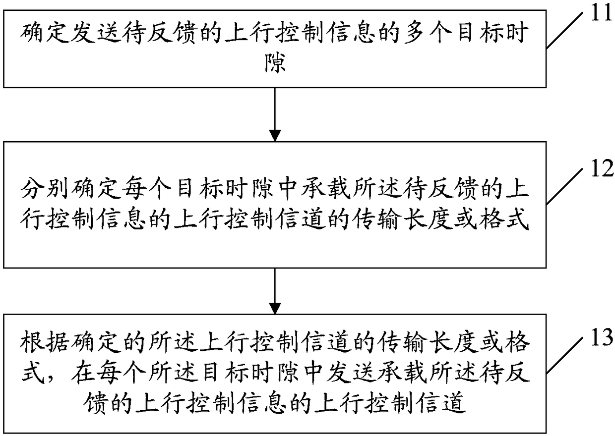
[0135] Such as figure 1 As shown, the embodiment of the present invention provides a method for sending an uplink control channel, including:

[0136] Step 11, determining a plurality of target time slots for sending the uplink control information to be fed back, wherein the uplink control information to be fed back is sent through an uplink control channel in the target time slots.

[0137] In this step, the method for sending the uplink control channel is generally applied to the terminal side, that is, the terminal determines the uplink control information UCI to be fed back, and determines that the UCI to be fed back is transmitted through the uplink control channel in multiple target time slots.

[0138] Step 12, respectively determining the transm...


PUM


Abstract

The invention provides a transmitting method, a receiving method, a device, a terminal and a base station for an uplink control channel. The transmitting method comprises the following steps: determining a plurality of target time slots for transmitting uplink control information to be fed back, wherein, the uplink control information to be fed back is transmitted through an uplink control channelin the target time slot; determining a transmission length or format of an uplink control channel carrying the uplink control information to be fed back in each target time slot; according to the determined transmission length or format of the uplink control channel, transmitting the uplink control channel carrying the uplink control information to be fed back in each of the target time slots, thereby realizing the purpose of uplink control channel transmission in a plurality of time slots.

Description

technical field [0001] The present invention relates to the field of communication technology, in particular to a sending method, a receiving method, a device, a terminal and a base station of an uplink control channel. Background technique [0002] With the development and change of mobile communication service requirements, organizations such as ITU (International Telecommunication Union, International Telecommunication Union) and 3GPP have begun to study new wireless communication systems (such as 5G New Radio Interface (5G NR, 5Generation New RAT)). A new frame structure is defined in a new wireless communication system, which supports different baseband parameters (numerology, including parameters such as subcarrier spacing, etc.). For different baseband parameters, it is defined that the length of a subframe is always 1ms, and a subframe contains A slots (slots), corresponding to different baseband parameters, the number of A may be different to meet the length of a su...

Claims


Application Information

Patent Timeline
IPC IPC(8): H04W72/12
CPCH04W72/21H04L5/0053H04L5/0048H04L5/0007H04L1/0006H04L1/0013H04W72/0446H04W72/535
Inventor 高雪娟
Owner DATANG MOBILE COMM EQUIP CO LTD
Why Eureka
Try Eureka