Supercharge Your Innovation With Domain-Expert AI Agents!

Pouring gate valve needle control device for injection mold

An injection mold and control device technology, applied in the field of injection mold valve needle control device, can solve problems such as flow marks, weld marks, and poor molding, achieve flexible and controllable speed and pressure, improve quality, and avoid poor flow marks Effect

Pending Publication Date: 2019-01-08
哈希斯热流道科技(苏州)有限公司
View PDF17 Cites 0 Cited by
  • Summary
  • Abstract
  • Description
  • Claims
  • Application Information

AI Technical Summary

Problems solved by technology

[0003] However, the traditional hot runner injection mold that relies on the sequencer to open and close the gates sequentially has defects, because the valve needle in the first gate and the valve pin on the second gate that is opened in sequence are controlled by the cylinder respectively, and flow into the cylinder. And the amount of compressed air discharged from the cylinder is constant. In fact, the valve needle in the first glue port and the valve needle of the second glue port are opened and closed at the same speed. Therefore, the subsequent passage through the second glue port The molten resin injected into the cavity has been injected with the maximum filling volume and maximum filling pressure at the initial stage of injection. When it merges with the molten resin injected through the first gate and flows towards the second gate, the surface may There will be flow marks and weld marks, resulting in poor molding and need to be improved

Method used


Image

  • Pouring gate valve needle control device for injection mold
  • Pouring gate valve needle control device for injection mold
  • Pouring gate valve needle control device for injection mold

Examples


Embodiment 1

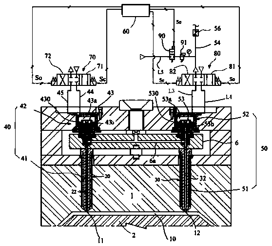
[0048] The second solenoid valve 80 is connected with the downstream side air discharge pipeline 54 corresponding to the third pipeline L3, and the throttle valve 56 is arranged on the downstream side air discharge pipeline 54 to discharge the second solenoid valve 80. Air flow control.

Embodiment 2

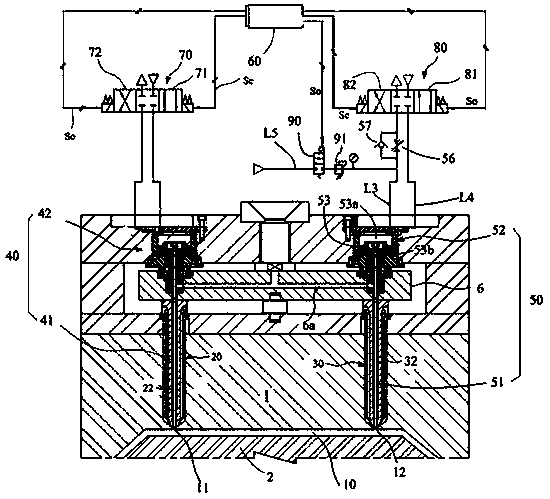
[0050] The throttle valve 56 is arranged on the third pipeline L3, and the third pipeline L3 is provided with a check valve 57 connected in parallel with the throttle valve 56, which passes through one way, so that the supply through the third pipeline L3 The compressed air in the upper cylinder chamber of the third cavity 53a can bypass the throttle valve 56 to ensure the closing speed of the second glue port 12 .

Embodiment 3

[0052] The throttle valve 56 is arranged on the discharge passage L32 of the second solenoid valve 80, and has a simple structure.

[0053] In addition, in order to have a stable back pressure on the pipeline where the throttle valve 56 is located, the auxiliary compressed air pipeline L5 can also be added, and the auxiliary compressed air pipeline L5 is connected to the third pipeline L3 or the downstream air discharge pipeline 54. connection, the compressed air auxiliary pipeline L5 is provided with an auxiliary solenoid valve 90 and a pressure reducing valve 91, the auxiliary solenoid valve 90 is linearly connected with the control part 60, and the control part 60 is used to control the auxiliary solenoid valve 90, by reducing The pressure valve 91 reduces the pressure of the supplementary compressed air to a certain value, maintains a certain pressure back pressure on the pipeline where the throttle valve 56 is located, and makes the action more stable;


PUM


Abstract

The invention discloses a pouring gate valve needle control device for an injection mold. The pouring gate valve needle control device comprises a cavity, a first nozzle, a second nozzle, a first pouring gate needle valve device, a second pouring gate needle valve device, a first electromagnetic valve, a second electromagnetic valve, a throttling valve and a control component, wherein the controlcomponent comprises a timing device linearly connected with the first electromagnetic valve and the second electromagnetic valve to control the first electromagnetic valve and the second electromagnetic valve to operate. Due to the mode, the injection mold pouring gate valve needle control device disclosed by the invention particularly adopts the throttling valve and a compressed air auxiliary pipeline, so that the opening speed of a subsequently opened second valve needle is lower than that of a previously opened first valve needle; the amount of molten resin injected into the cavity througha second pouring gate is reduced, and poor rill marks in a confluence point or a confluence area of the molten resin is avoided.

Description

technical field [0001] The invention relates to the field of injection molds, in particular to a control device for a valve needle at a rubber port of an injection mold. Background technique [0002] The control method of the traditional multi-port hot runner injection mold is usually to control the solenoid valve according to the preset sequencer control signal, so that the valve pins of the ports can be controlled sequentially. According to the way the sequencer controls the gate valve needle, the valve needle on one gate opens first, and then the resin flows into the cavity. During the cavity filling process, the valve needle on the second gate opens again, and flows into the same mold. The molten resin is continuously injected into the cavity, and the molten resin injected into the cavity after the second glue port is opened is fused with the molten resin injected into the cavity by the first glue port to fill the entire cavity. [0003] However, the traditional hot run...

Claims


Application Information

Patent Timeline
Patent Type & Authority Applications(China)
IPC IPC(8): B29C45/28B29C45/77
CPCB29C45/2803B29C45/281B29C45/77B29C2945/76498B29C2945/76595
Inventor 许南旭
Owner 哈希斯热流道科技(苏州)有限公司
Features
  • R&D
  • Intellectual Property
  • Life Sciences
  • Materials
  • Tech Scout
  • Unparalleled Data Quality
  • Higher Quality Content
  • 60% Fewer Hallucinations
Learn More