Supercharge Your Innovation With Domain-Expert AI Agents!

Inverter system and phase-locking method thereof

An inverter and phase-locking technology, applied in the phase-locking control unit and its phase-locking field, can solve the problems of unstable operation of the parallel system and large circulating current, and achieve the effects of preventing jitter and flexible and controllable speed.

Active Publication Date: 2008-09-17
VERTIV CORP
View PDF3 Cites 0 Cited by
  • Summary
  • Abstract
  • Description
  • Claims
  • Application Information

AI Technical Summary

Problems solved by technology

[0008] Aiming at the above-mentioned defects of the prior art, the present invention solves the problem that the operation of the parallel system will be unstable when the bypass frequency changes greatly in the phase-locking method of the prior art, especially to solve the problem of dynamic phase tracking of the parallel system. Problems with large circulating currents during transitions to enhance reliability of paralleled systems

Method used


Image

  • Inverter system and phase-locking method thereof
  • Inverter system and phase-locking method thereof
  • Inverter system and phase-locking method thereof

Examples


Embodiment Construction

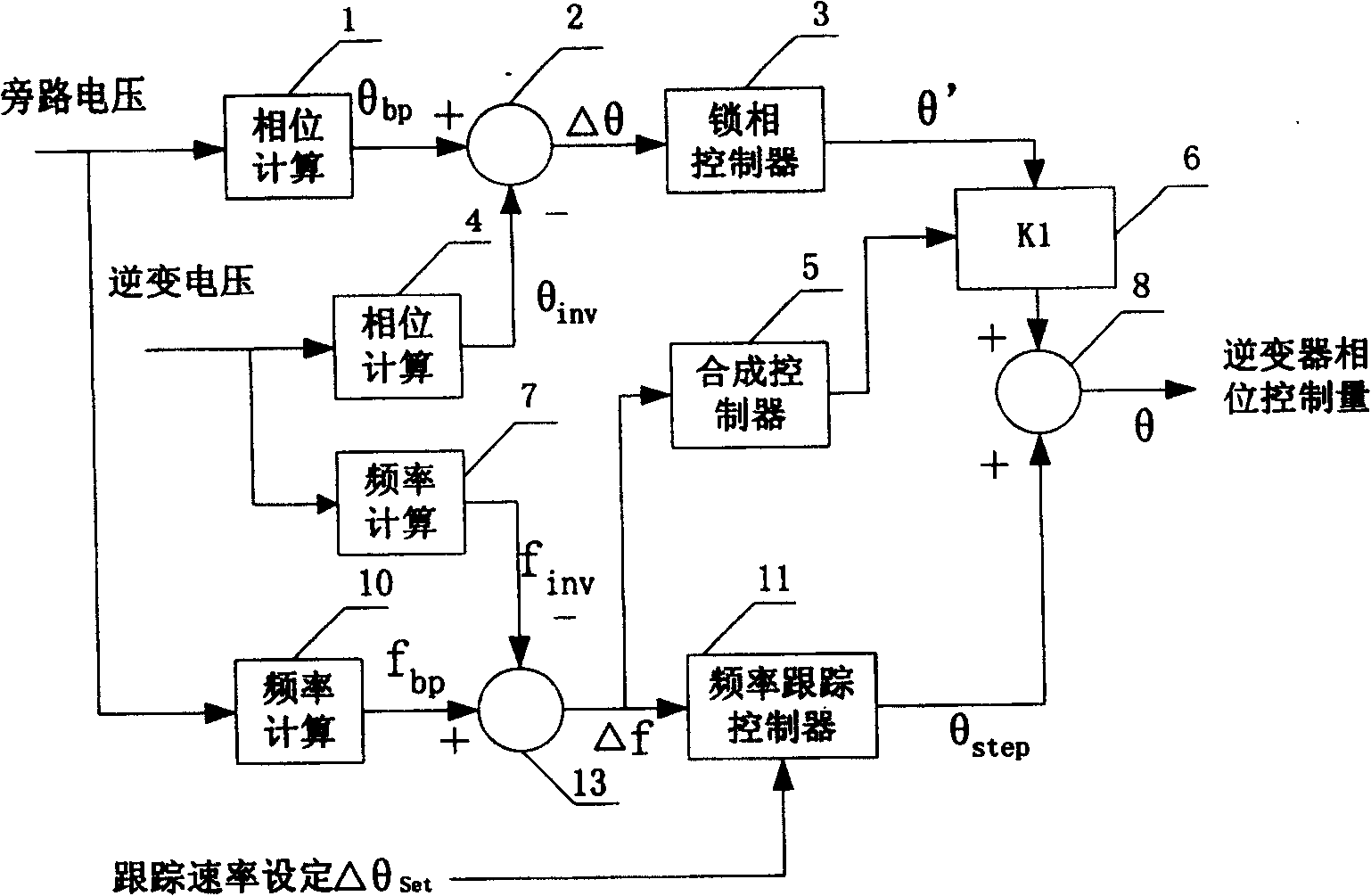
[0020] like image 3 A preferred embodiment of the invention is shown.

[0021] It can be seen from the figure that the bypass voltage is input into the bypass phase calculator 1 and the bypass frequency calculator 10 respectively, thereby calculating the phase θ of the bypass voltage bp and frequency f bp .

[0022] Similarly, the inverter output voltage is input into the inverter phase calculator 4 and the inverter frequency calculator 7 respectively, thereby calculating the phase θ of the inverter output voltage inv and frequency f inv .

[0023] Then, the phase θ of the bypass voltage is calculated by the first subtractor 2 bp Subtract the phase θ of the inverter output voltage inv The resulting phase difference Δθ. Then, the phase difference Δθ is input to the phase-locked controller 3 for adjustment to generate a first adjustment amount θ′. The phase-locked controller 3 may be a PID (proportional-integral-derivative) controller, or a PI (proportional-integral) co...


PUM


Abstract

The present invention relates to one kind of inverter system with raised stability. In the phase-locking control unit, the first subtracter calculates the phase different between by-pass voltage and the inverter output voltage, and the first phase-locking controller regulates the phase difference to generate the first regulation amount. The second subtracter calculates the frequency difference between by-pass voltage and the inverter output voltage, and the frequency tracking controller generates the second regulation amount based on the frequency difference and set tracking rate. Then, the second phase-locking controller generates the third regulation amount based on the first regulation amount, and the second adder adds the second regulation amount and the third regulation amount to obtain the phase control amount of the inverter system for phase locking. The second phase-locking controller includes a multiplier to output the third regulation amount.

Description

technical field [0001] The invention relates to an inverter system, in particular to a phase-locked control unit in the inverter system and a phase-locked method thereof, which can be applied to a parallel inverter system to make the output voltage of the inverter in phase with a given target voltage , so that the parallel inverter system is more stable. Background technique [0002] With the development of IT (information technology) technology, the reliability requirements of IT equipment for power supply are getting higher and higher. In order to meet the high requirements of IT equipment for power supply, large-capacity UPS (uninterruptible power supply) generally adopts parallel redundant mode. , to increase the reliability of the system. [0003] figure 1 It is a schematic diagram of a UPS system, which includes a rectifier unit and an inverter unit (composed of capacitors C1, C2, switch tubes K1, K2, inductor L and capacitor C) behind the rectifier unit. The input ...

Claims


Application Information

Patent Timeline
Patent Type & Authority Patents(China)
IPC IPC(8): H02M7/48
Inventor 盛小军卓清锋周党生
Owner VERTIV CORP
Features
  • R&D
  • Intellectual Property
  • Life Sciences
  • Materials
  • Tech Scout
  • Unparalleled Data Quality
  • Higher Quality Content
  • 60% Fewer Hallucinations
Learn More