A deployment mechanism of a parabolic cylindrical antenna reflector with high accommodation ratio

An antenna reflector and unfolding mechanism technology, which is applied to antennas, electrical components, etc., can solve the problems of complicated unfolding process, large folding size, and difficult engineering realization, and achieve high scalability, high storage ratio, and avoid structural interference. Effect

Active Publication Date: 2019-01-08
XIAN INSTITUE OF SPACE RADIO TECH
View PDF8 Cites 2 Cited by
  • Summary
  • Abstract
  • Description
  • Claims
  • Application Information

AI Technical Summary

Problems solved by technology

In the design of some unfolding mechanisms of parabolic reflectors, they often have a large folded size, and the unfolding process is complicated, which is not easy to realize in engineering

Method used


Image

  • A deployment mechanism of a parabolic cylindrical antenna reflector with high accommodation ratio
  • A deployment mechanism of a parabolic cylindrical antenna reflector with high accommodation ratio
  • A deployment mechanism of a parabolic cylindrical antenna reflector with high accommodation ratio

Examples


Embodiment

[0041] For the designed deployment mechanism, a set of size and angle parameters are set, and the simulation analysis is carried out. The length dimensions are shown in the table below:

[0042]

[0043]

[0044] The angle parameters are shown in the table below:

[0045] Fixed Angle Parameter

Unit (°)

θ 1

11.8

θ 2

135

θ 3

90

θ 4

135

[0046] After motion analysis, the parameters of the key angles of the unfolding mechanism can be obtained, as shown in the following table.

[0047]

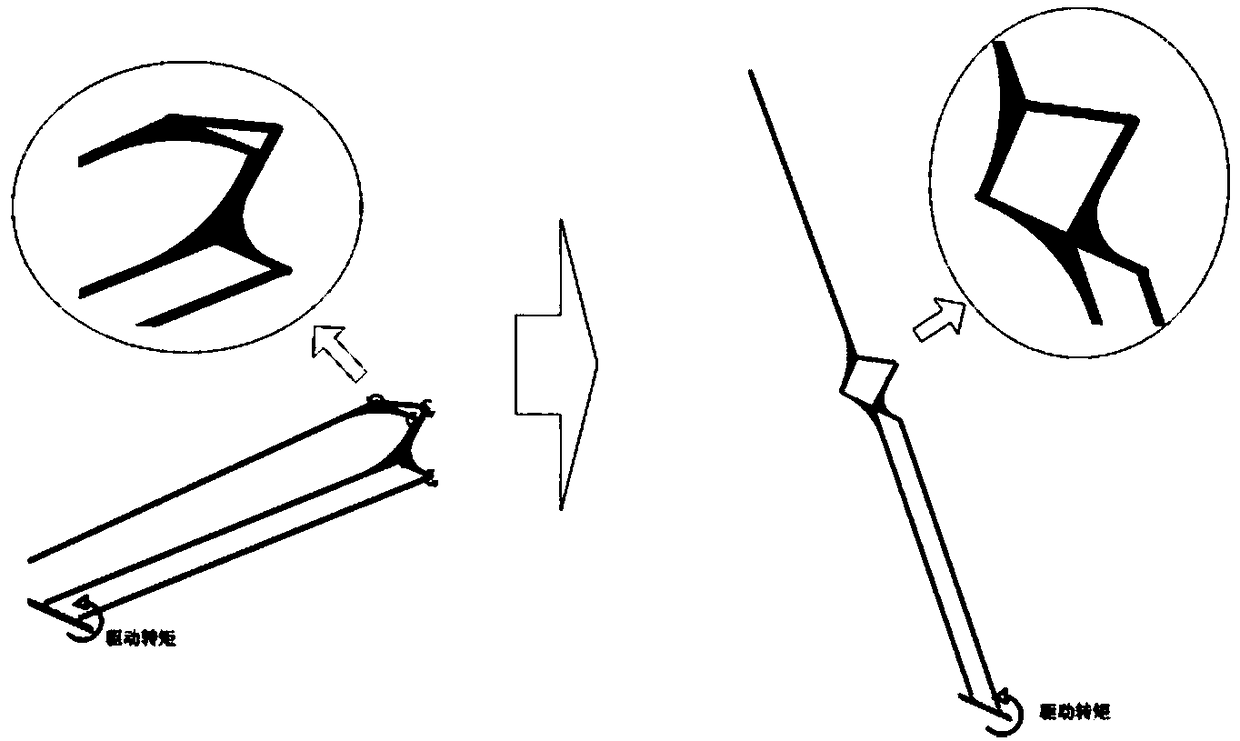
[0048] The position of the kinematic model of the unfolding mechanism at the 0 / 1.9 / 5.7 / 7.6s sampling point during the unfolding process is as follows: Figure 6 (a)~ Figure 6 (d) shown.


PUM


Abstract

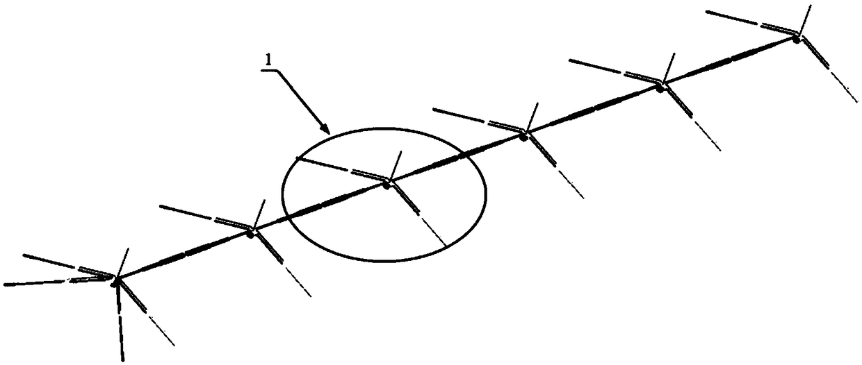
A deployment mechanism of a parabolic cylindrical antenna reflector with a high accommodation ratio comprises a plurality of groups of M-shaped antenna reflector deployment mechanisms (1); Each groupof M-shaped antenna reflector deployment mechanism (1) is installed on the support truss; The M-shaped antenna reflector deployment mechanism (1) is of a symmetrical structure and comprises a power source (3), a middle fixed mandrel (10) and a linkage mechanism; A sliding pair is established between the power source (3) and the intermediate fixed mandrel (10), A linkage mechanism is connected withthat central fixed mandrel (10) and the power source (3) through a rotating pair, the linkage mechanism is symmetrical about the central fixed mandrel (10), and under the driving action of the powersource (3), the power source (3) slides along the central fixed mandrel (10), thereby driving the linkage mechanism to expand in a plane. The invention solves the parabolic cylindrical surface application problem that 50m or longer size is difficult to realize in the current space mission, and provides a solution for a space large parabolic cylindrical deployable antenna.

Description

technical field [0001] The invention relates to an antenna reflector deployment mechanism, which belongs to the field of satellite deployment antennas. Background technique [0002] A variety of tasks in space require a parabolic cylinder antenna. The antenna reflector has an extremely long dimension along the axis of the cylinder, such as 50m or even larger, and the dimension along the opening direction is about 5-10m. A large antenna of this size needs to be applied in space, and due to the limitation of the carrying envelope, it must be designed to be expandable. That is, when the antenna transmits uplink, the antenna system is gathered in a smaller envelope size, and after the constraint is released on orbit, the mechanism is used to expand to achieve the required antenna form. At the same time, the deployment mechanism of the antenna reflector needs to have high reliability and controllability. [0003] For the required spaceborne deployable parabolic antenna, the cur...

Claims


Application Information

Patent Timeline
Patent Type & Authority Applications(China)
IPC IPC(8): H01Q15/16
CPCH01Q15/161
Inventor 李洋马小飞李团结郑士昆黄志荣朱佳龙杨军刚张恒超赵将
Owner XIAN INSTITUE OF SPACE RADIO TECH
Why Eureka
Try Eureka