Circular Cross Cable Net Antenna
A technology of crossing cables and cable nets, which is applied in the field of satellite antennas, can solve problems such as poor structural stability of asymmetric cable nets and changes in the accuracy of antenna profiles, and achieve good structural stability, good profile accuracy, and small weight.
- Summary
- Abstract
- Description
- Claims
- Application Information
AI Technical Summary
Problems solved by technology
Method used
Image
Examples
Embodiment 1
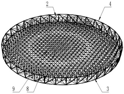
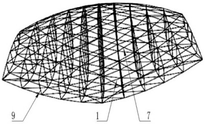
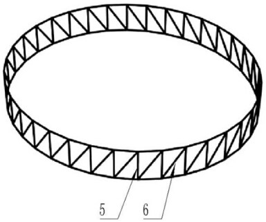
[0022] Such as figure 1 , figure 2 and image 3 As shown, the circular cross cable-net antenna includes a circular truss 4 and a front cable network 2 and a rear cable network 3 formed by interlacing cables 1. The circular truss 4 includes a plurality of vertical rods 5 and diagonal rods 6 in equal numbers. , the vertical rods 5 and the oblique rods 6 are arranged at intervals, and the ends are connected in turn to form a circular curved surface in the vertical direction. The node 7 on the top is correspondingly connected with the joint of the vertical bar 5 and the diagonal bar 6 at the top of the ring truss 4, and the joint of the node 7 on the circumference of the rear cable net 3 is connected with the vertical bar 5 and the diagonal bar 6 at the bottom of the ring truss 4 Corresponding connection, the front cable net 2 and the rear cable net 3 are parabolic and symmetrically arranged, the nodes 7 corresponding to the non-intersecting parts of the front cable net 2 and t...
Embodiment 2
[0025] Such as figure 1 and figure 2 As shown, the cables 1 on the front cable net 2 are interlaced to form a triangular grid, and the cables 1 on the rear cable net 3 are interlaced to form a triangular grid.
[0026] Between the node 7 on the front cable net 2 and the ring truss 4, between the node 7 on the front cable net 2 and the flexible rope 8, between the node 7 on the front cable net 2 and the support rod 9, between the rear cable net Between the node 7 on the truss 3 and the ring truss 4, between the node 7 on the rear cable net 3 and the flexible rope 8, between the node 7 on the rear cable net 3 and the support rod 9 are all connected by binding.
[0027] The triangular grid structure has good geometric strength and high reliability, and the way of bundling connection further increases the reliability of the circular cross cable-net antenna.
Embodiment 3
[0029] Such as Figure 4 and Figure 5 As shown, the front cable net 2 and the rear cable net 3 are completely symmetrical about the plane of symmetry 10 , the plane of symmetry 10 is located in the middle of the ring truss 4 and is parallel to the cross section of the ring truss 4 .
[0030] The grids of the front cable net 2 and the rear cable net 3 are both quasi-geodesic grids, which are six circles respectively, and the grids of the front cable net 2 and the rear cable net 3 overlap in the third circle.
[0031] The focal-diameter ratios of the front cable net 2 and the rear cable net 3 are both 0.4.
[0032] The cable 1 force of the cable 1 is 100N.
[0033] The diameter of the rotating paraboloid of the antenna is 12m.
[0034] Examples:
[0035] The diameter of the rotating parabolic antenna is 12m, the focal-diameter ratio of the front cable net 2 (reflector) is 0.4, the front and rear cable nets 3 are completely symmetrical, and the force requirements of the cabl...
PUM
 Abstract
Description
Claims
Application Information
 - R&D
- Intellectual Property
- Life Sciences
- Materials
- Tech Scout
- Unparalleled Data Quality
- Higher Quality Content
- 60% Fewer Hallucinations
Browse by: Latest US Patents, China's latest patents, Technical Efficacy Thesaurus, Application Domain, Technology Topic, Popular Technical Reports.
© 2025 PatSnap. All rights reserved.Legal|Privacy policy|Modern Slavery Act Transparency Statement|Sitemap|About US| Contact US: help@patsnap.com


