Circular cross cable antenna

A cross-cable and ring-shaped technology, applied in the field of satellite antennas, can solve the problems of poor structural stability of asymmetric cable nets and changes in antenna profile accuracy, and achieve the effects of good structural stability, good profile accuracy, and reduced quality.

Active Publication Date: 2018-07-20
XIDIAN UNIV
View PDF8 Cites 9 Cited by
  • Summary
  • Abstract
  • Description
  • Claims
  • Application Information

AI Technical Summary

Problems solved by technology

[0003] In order to solve the problem that the stability of the asymmetric cable net structure is poor in the space temperature environment, resulting in a large change in the precision of the antenna profile, the present invention provides a circular cross cable net antenna, which has a stable structure and high profile precision. The folded antenna has the advantages of small size and mass, no need for many unfolding joints, etc.

Method used


Image

  • Circular cross cable antenna
  • Circular cross cable antenna
  • Circular cross cable antenna

Examples


Embodiment 1

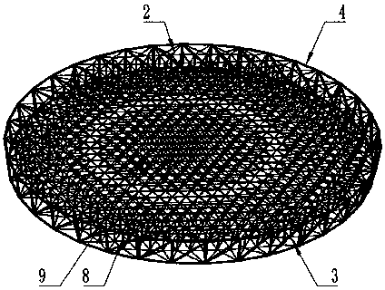
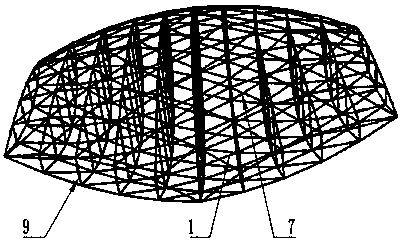
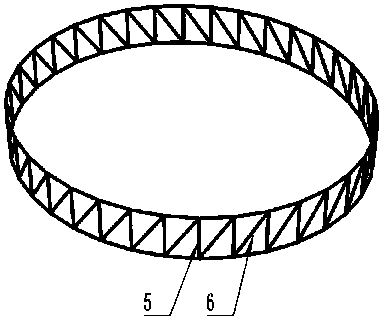
[0022] Such as figure 1 , figure 2 and image 3 As shown, the circular cross cable-net antenna includes a circular truss 4 and a front cable network 2 and a rear cable network 3 formed by interlacing cables 1. The circular truss 4 includes a plurality of vertical rods 5 and diagonal rods 6 in equal numbers. , the vertical rods 5 and the oblique rods 6 are arranged at intervals, and the ends are connected in turn to form a circular curved surface in the vertical direction. The node 7 on the top is correspondingly connected with the joint of the vertical bar 5 and the diagonal bar 6 at the top of the ring truss 4, and the joint of the node 7 on the circumference of the rear cable net 3 is connected with the vertical bar 5 and the diagonal bar 6 at the bottom of the ring truss 4 Corresponding connection, the front cable net 2 and the rear cable net 3 are parabolic and symmetrically arranged, the nodes 7 corresponding to the non-intersecting parts of the front cable net 2 and t...

Embodiment 2

[0025] Such as figure 1 and figure 2 As shown, the cables 1 on the front cable net 2 are interlaced to form a triangular grid, and the cables 1 on the rear cable net 3 are interlaced to form a triangular grid.

[0026] Between the node 7 on the front cable net 2 and the ring truss 4, between the node 7 on the front cable net 2 and the flexible rope 8, between the node 7 on the front cable net 2 and the support rod 9, between the rear cable net Between the node 7 on the truss 3 and the ring truss 4, between the node 7 on the rear cable net 3 and the flexible rope 8, between the node 7 on the rear cable net 3 and the support rod 9 are all connected by binding.

[0027] The triangular grid structure has good geometric strength and high reliability, and the way of bundling connection further increases the reliability of the circular cross cable-net antenna.

Embodiment 3

[0029] Such as Figure 4 and Figure 5 As shown, the front cable net 2 and the rear cable net 3 are completely symmetrical about the plane of symmetry 10 , the plane of symmetry 10 is located in the middle of the ring truss 4 and is parallel to the cross section of the ring truss 4 .

[0030] The grids of the front cable net 2 and the rear cable net 3 are both quasi-geodesic grids, which are six circles respectively, and the grids of the front cable net 2 and the rear cable net 3 overlap in the third circle.

[0031] The focal-diameter ratios of the front cable net 2 and the rear cable net 3 are both 0.4.

[0032] The cable 1 force of the cable 1 is 100N.

[0033] The diameter of the rotating paraboloid of the antenna is 12m.

[0034] Examples:

[0035] The diameter of the rotating parabolic antenna is 12m, the focal-diameter ratio of the front cable net 2 (reflector) is 0.4, the front and rear cable nets 3 are completely symmetrical, and the force requirements of the cabl...


PUM


Abstract

The present invention provides a circular cross cable antenna which comprises an annular truss and a front cable net and a back cable net which are interlaced by cables. The annular truss comprises aplurality of vertical rods and inclined rods with the equal number. Nodes on the circumference of the front cable net are correspondingly connected to connection parts of the vertical rods and the inclined rods at the top of the annular truss, the front cable net and the back cable net are paraboloids and are in symmetrical arrangement, nodes corresponding to non-intersecting parts of the front cable net and the back cable net are connected by flexible ropes, and nodes corresponding to intersecting parts of the front cable net and the back cable net are connected by support rods. According tothe circular cross cable antenna, a ring-shaped expandable structure is adopted, so the weight is small, the profile precision is good, the storage ratio is high, the excessive arch height is avoided,the overlarge antenna folding size is avoided, the weight of the antenna is reduced, symmetrical cable net structures are used by front and back cable net surfaces, and the good structural stabilityis provided.

Description

technical field [0001] The invention relates to the technical field of satellite antennas, in particular to a circular cross cable-net antenna. Background technique [0002] Loop deployable antennas have been extensively researched and applied in the aerospace field due to their small weight, good surface accuracy, and high storage ratio. The annular deployable antenna reflector is mainly composed of cable net structure, front and rear cable net, metal mesh and truss, among which the cable net structure is the core part of the reflector profile, and the annular deployable antenna is folded in the fairing of the rocket during launch. After entering the orbit, the antenna is stretched out of the star through the unfolding arm, so the loop antenna will be restricted by these two states when designing the mesh surface. First of all, the focal length selection of the front and rear cable nets will be limited by the size of the antenna. If the focal length is too small, the size ...

Claims


Application Information

Patent Timeline
Patent Type & Authority Applications(China)
IPC IPC(8): H01Q1/36H01Q1/12H01Q1/08
CPCH01Q1/085H01Q1/1235H01Q1/36
Inventor 杨东武谭国栋张涛郭王策王虹樽
Owner XIDIAN UNIV
Why Eureka
Try Eureka