Manufacturing equipment for monitors

A monitor and equipment technology, applied in the field of monitor manufacturing equipment, can solve the problems of low detector processing efficiency, cumbersome operation steps, single drilling function, etc., and achieve increased rotation flexibility, improved work efficiency, and clamping work. Simple and convenient effect

Inactive Publication Date: 2019-01-11
泉州市华泽数字科技有限公司
View PDF5 Cites 2 Cited by
  • Summary
  • Abstract
  • Description
  • Claims
  • Application Information

AI Technical Summary

Problems solved by technology

[0002] At present, when the detector is prepared and processed, it is necessary to drill the detector shell. The current drilling equipment usually only has a single drilling function, so that it is necessary to repeat the drilling operation many times when drilling. For The processing efficiency of the detector is low, and during processing, when the detector is clamped, manual adjustment is required. The operation steps are cumbersome and need to be improved

Method used


Image

  • Manufacturing equipment for monitors
  • Manufacturing equipment for monitors

Examples


Embodiment Construction

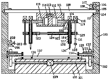
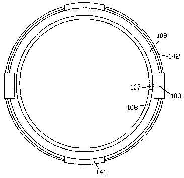
[0017] Combine below Figure 1-2 The present invention will be described in detail.

[0018] refer to Figure 1-2 , according to an embodiment of the present invention, a monitor manufacturing equipment includes a bottom plate 100 and supports 103 symmetrically fixed on the left and right sides of the bottom plate 100, and the supports 103 on the left and right sides are rotated and matched A turntable 109 is installed, the bottom end of the turntable 109 is fixed with a production frame 111, and the left and right symmetrical air pressure chambers 115 are arranged in the said production frame 111, and a pushing plate 112 is installed in the said air pressure chamber 115 for sliding fit, left and right An adjustment frame 122 is fixed on the opposite side of the pushing plates 112 on both sides. The adjustment frame 112 protrudes from the outer end of the production frame 111 and is connected with it by sliding fit. The top wall of the air pressure chamber 115 Connected with...


PUM


Abstract

The invention discloses manufacturing equipment for monitors. The manufacturing equipment comprises a bottom plate and supports, wherein the supports are fixedly arranged on the left and right sides of the bottom plate in a bilateral symmetry mode. A rotating frame is mounted between the supports on the left and right sides in a rotating fit mode. A production frame is fixedly arranged on the bottom end face of the rotating frame. Air pressure cavities are formed in the production frame in a bilateral symmetry mode. Pushing plates are mounted in the air pressure cavities in a sliding fit mode.Adjusting frames are fixedly arranged on the end faces of the opposite sides of the pushing plates on the left and right sides, and the adjusting frames stretch out of the outer side end of the production frame and are connected with the production frame in a sliding fit mode. Air pressure holes are formed in the top walls of the air pressure cavities in a communicating mode. The air pressure holes in the left and right sides are connected with an air pressure cylinder which is fixedly arranged in the production frame. First penetrating grooves are formed in the adjusting frames stretching out of the outer side end of the production frame in a vertically penetrating mode, and spline shafts are mounted in the first penetrating grooves in a clearance fit mode.

Description

technical field [0001] The invention relates to the technical field of detector processing, in particular to a monitor manufacturing equipment. Background technique [0002] At present, when the detector is prepared and processed, it is necessary to drill the detector shell. The current drilling equipment usually only has a single drilling function, so that it is necessary to repeat the drilling operation many times when drilling. For The processing efficiency of the detector is low, and during processing, when the detector is clamped, manual adjustment is required, and the operation steps are cumbersome and need to be improved. Contents of the invention [0003] The purpose of the present invention is to provide a monitor manufacturing equipment for overcoming the above-mentioned defects in the prior art. [0004] A monitor manufacturing device according to the present invention includes a bottom plate and supports symmetrically fixed on the left and right sides of the b...

Claims


Application Information

Patent Timeline
IPC IPC(8): B23B39/16B23B41/00
Inventor 邓英樊云枝曾强盛
Owner 泉州市华泽数字科技有限公司
Why Eureka
Try Eureka