
Rapid forming method of fiber reinforced composite material plate

A composite material and fiber-reinforced technology, which is applied in metal processing and other directions, can solve the problems of low processing efficiency, single drilling function, and cumbersome operation steps of composite material plates, and achieve increased rotation flexibility, simple and convenient clamping work, and improved The effect of work efficiency

Inactive Publication Date: 2019-01-15
惠安县正和机械设备有限公司
View PDF0 Cites 0 Cited by
  • Summary
  • Abstract
  • Description
  • Claims
  • Application Information

AI Technical Summary

Problems solved by technology

[0002] At present, when preparing and processing composite material plates, drilling work is required. The current drilling equipment usually only has a single drilling function, so that it is necessary to repeat multiple drilling operations during drilling. For composite material plates The processing efficiency is low, and during processing, when clamping composite material plates, manual adjustment is required, and the operation steps are cumbersome and need to be improved

Method used


Image

  • Rapid forming method of fiber reinforced composite material plate
  • Rapid forming method of fiber reinforced composite material plate

Examples


Embodiment Construction

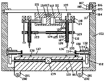
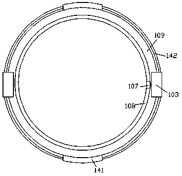
[0017] Combine below Figure 1-2 The present invention will be described in detail.

[0018] refer to Figure 1-2 , according to an embodiment of the present invention, a rapid prototyping method for a fiber-reinforced composite material plate, comprising a base plate 100 and vertical frames 103 symmetrically fixed on the left and right sides of the base plate 100, and the vertical frames 103 on the left and right sides A swivel ring 109 is installed in rotation between them, and the bottom end surface of the swivel ring 109 is fixed with a manufacturing frame 111, and the left and right symmetrical air pressure chambers 115 are arranged in the manufacturing frame 111, and a compression plate is installed in the air pressure chamber 115 for sliding fit. 112, the left and right sides of the compression plate 112 on the opposite side are fixed with a distance adjustment frame 122, and the distance adjustment frame 112 protrudes from the outer end of the manufacturing frame 111 ...


PUM


Abstract

The invention discloses a rapid forming method of a fiber reinforced composite material plate. A device comprises a base plate and vertical frames, wherein the vertical frames are fixedly arranged onthe left side and the right side of the base plate in a left-and-right symmetry mode. A rotating ring is installed between the vertical frames on the left side and the right side in a running fit mode, and a manufacturing frame is fixedly arranged on the end face of the bottom of the rotating ring. Air pressure cavities are formed in the manufacturing frame in a left-and-right symmetry mode, and compression plates are installed in the air pressure cavities in a sliding fit mode. Distance adjusting frames are fixedly arranged on the end faces of the opposite sides of the compression plates on the left side and the right side, stretch out of the outer side end of the manufacturing frame and are connected with the manufacturing frame in a sliding fit mode. Air pressure holes are formed in thetop walls of the air pressure cavities in a communicating mode, the air pressure holes formed in the left side and the right side are connected with an air pressure cavity, and the air pressure cylinder is fixedly arranged in the manufacturing frame. First hole grooves are formed in the distance adjusting frames in a vertical penetration mode, the distance adjusting frames stretch out of the outer side end of the manufacturing frame, and splined shafts are installed in the first hole grooves in a clearance fit mode.

Description

technical field [0001] The invention relates to the technical field of composite material plate processing, in particular to a rapid prototyping method for fiber-reinforced composite material plates. Background technique [0002] At present, when preparing and processing composite material plates, drilling work is required. The current drilling equipment usually only has a single drilling function, so that it is necessary to repeat multiple drilling operations during drilling. For composite material plates The processing efficiency is low, and during processing, when clamping composite material plates, manual adjustment is required, and the operation steps are cumbersome and need to be improved. Contents of the invention [0003] The object of the present invention is to provide a rapid prototyping method for fiber-reinforced composite material plates, which is used to overcome the above-mentioned defects in the prior art. [0004] A rapid prototyping method for fiber-rei...

Claims


Application Information

Patent Timeline
Patent Type & Authority Applications(China)
IPC IPC(8): B26F1/16B26D5/06B26D5/08B26D7/02B26D7/26
CPCB26F1/16B26D5/06B26D5/086B26D7/025B26D7/2628
Inventor 张金发
Owner 惠安县正和机械设备有限公司
Learn More