Adjustable automatic welding device for machining

A mechanical processing and automatic welding technology, applied in the field of mechanical processing, can solve problems such as limiting the scope of welding, and achieve the effects of increasing stability, strong practicability and strong adaptability

Inactive Publication Date: 2019-01-11
新昌县利安轴承有限公司
View PDF0 Cites 4 Cited by
  • Summary
  • Abstract
  • Description
  • Claims
  • Application Information

AI Technical Summary

Problems solved by technology

[0002] Automatic welding equipment for mechanical processing is an auxiliary working equipment for connecting metals. With the continuous development of society, automatic welding equipment also plays an important role in all walks of life. Although the existing automatic welding equipment on the market There are many types and quantities, but there are still some problems. For example, when the automatic welding equipment on the existing market is used for welding, the welding equipment is generally a fixed structure, and a transmission device is arranged on the worktable. The workpiece is placed on the transmission device. Welding is carried out through the movement of the workpiece, and the two ends are limited by the guide device. Only specific specifications and sizes can be welded, which limits the scope of welding. Therefore, we propose an adjustable automatic welding device for machining

Method used


Image

  • Adjustable automatic welding device for machining
  • Adjustable automatic welding device for machining
  • Adjustable automatic welding device for machining

Examples


Embodiment Construction

[0026] The following will clearly and completely describe the technical solutions in the embodiments of the present invention with reference to the accompanying drawings in the embodiments of the present invention. Obviously, the described embodiments are only some, not all, embodiments of the present invention. Based on the embodiments of the present invention, all other embodiments obtained by persons of ordinary skill in the art without making creative efforts belong to the protection scope of the present invention.

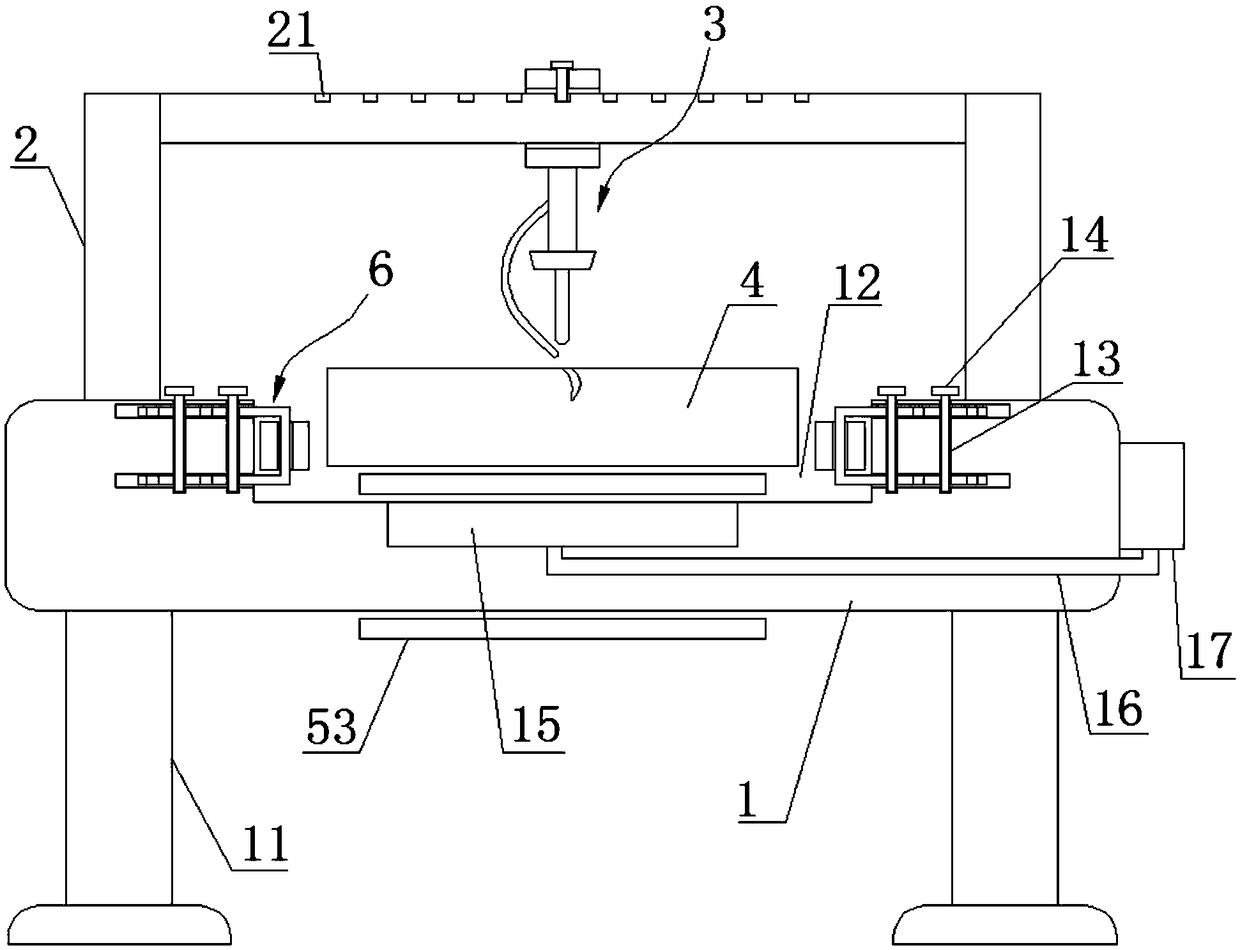
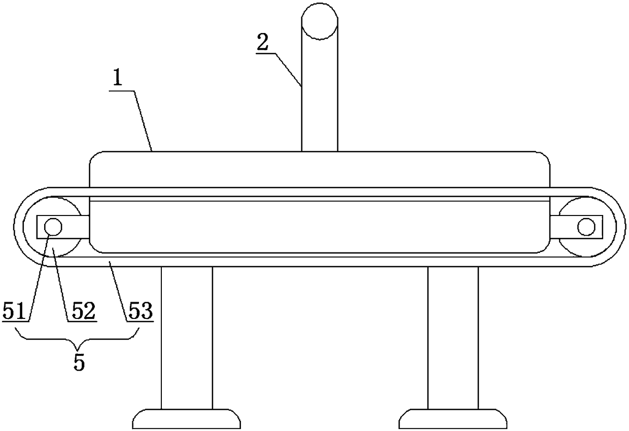
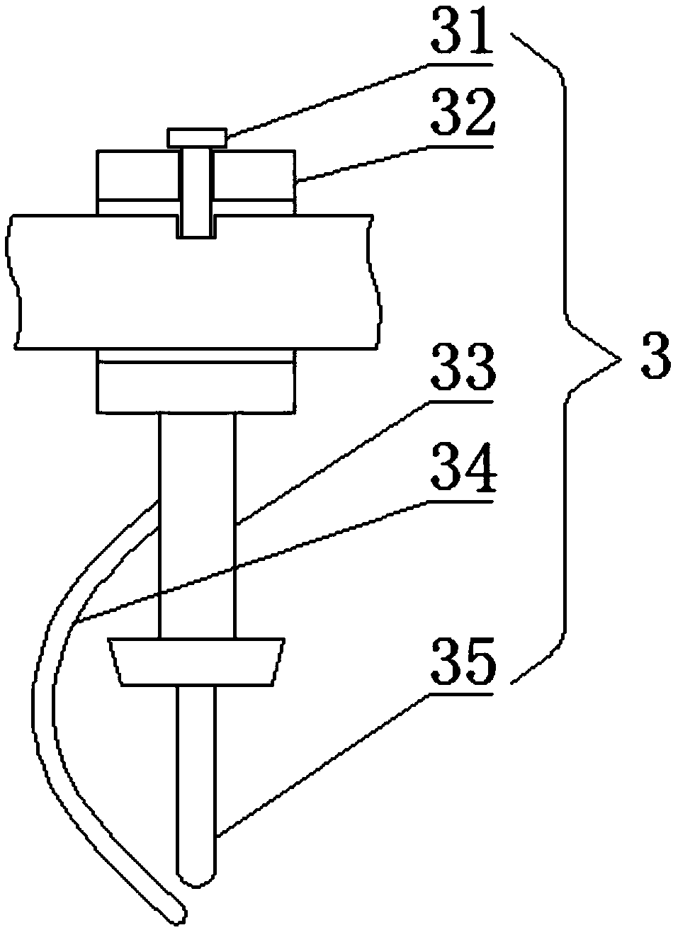
[0027] see Figure 1-4 , the present invention provides a technical solution:

[0028] An adjustable automatic welding device for mechanical processing, comprising a workbench 1 and a U-shaped frame 2 connected to the upper end surface of the workbench 1, the lower end surface of the workbench 1 is connected with four supporting feet 11, and The four supporting feet 11 are distributed in a matrix. The upper end of the workbench 1 is provided with a U-shaped g...


PUM


Abstract

The invention relates to the technical field of machining, in particular to an adjustable automatic welding device for machining. The upper end of a workbench is provided with a U-shaped groove, wherein the U-shaped groove is formed between two stand columns of a U-shaped bracket. The workbench is further provided with a conveying device. The conveying device is composed of rotating shafts, rollerwheels, a conveying belt and a motor, wherein the rotating shafts are connected to the front end face and the rear end face of the workbench in a rotary manner; each roller wheel is fixedly connectedto the corresponding rotating shaft in a sleeving manner; the conveying belt is used for connecting the two roller wheels; and the motor is connected with one end of one of the rotating shafts. The motor is mounted on the side end face of the workbench. The upper end of the conveying belt is connected with a welded workpiece, wherein the welded workpiece is located in the U-shaped groove. A transverse section of the U-shaped bracket is connected with a movable welding device. Two limiting and guiding devices are symmetrically connected to the side walls of the two ends of the U-shaped groovein an inserted manner. According to the adjustable automatic welding device for machining, the purpose of welding the different welded workpieces is achieved through multi-directional adjustment, andthe quite high practicability is achieved.

Description

technical field [0001] The invention relates to the technical field of machining, in particular to an adjustable automatic welding device for machining. Background technique [0002] Automatic welding equipment for mechanical processing is an auxiliary working equipment for connecting metals. With the continuous development of society, automatic welding equipment also plays an important role in all walks of life. Although the existing automatic welding equipment on the market There are many types and quantities, but there are still some problems. For example, when the automatic welding equipment on the existing market is used for welding, the welding equipment is generally a fixed structure, and a transmission device is arranged on the worktable. The workpiece is placed on the transmission device. Welding is carried out through the movement of the workpiece, and the two ends are limited by the guide device. Only specific specifications and sizes can be welded, which limits t...

Claims


Application Information

Patent Timeline
Patent Type & Authority Applications(China)
IPC IPC(8): B23K37/00B23K37/02
CPCB23K37/00B23K37/0211
Inventor 杨喜成杨佳魏
Owner 新昌县利安轴承有限公司
Why Eureka
Try Eureka