Wire connection device for field wiring of electric power

A wire connection and on-site technology, which is applied in the direction of connecting/disconnecting, connecting, and assembling/disassembling of contact pieces, etc., can solve problems such as low paralleling efficiency, inapplicability of long-length wires, and affecting wire connection efficiency

Active Publication Date: 2019-12-06
STATE GRID SHANDONG ELECTRIC POWER COMPANY WEIFANG POWER SUPPLY +1
View PDF4 Cites 0 Cited by
  • Summary
  • Abstract
  • Description
  • Claims
  • Application Information

AI Technical Summary

Problems solved by technology

[0003] The first method is manual paralleling, which will cause great harm to human hands during the process of paralleling. At the same time, the thread head is not firm after paralleling, and the wires are prone to drop or drop. The efficiency of paralleling is low; and it is easy to cause waste of wires;
[0004] The second method: use tools such as pliers to bend the wire, it is easy to scratch the wire when bending the wire, and the gap between the bent coils is large, which is not beautiful;
[0005] The third method is to install the wire clip and the sleeve on the electric drill, and drive the sleeve to rotate through the electric drill to make the external wires wrap around the main wire to achieve paralleling. However, the paralleling of the wires with the electric drill has poor versatility and is not suitable for long wires. It not only affects the efficiency of wire connection, but also affects the effect of wire connection

Method used


Image

  • Wire connection device for field wiring of electric power
  • Wire connection device for field wiring of electric power
  • Wire connection device for field wiring of electric power

Examples


Embodiment 1

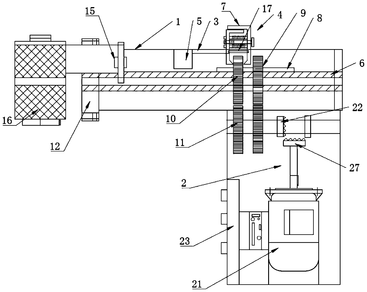
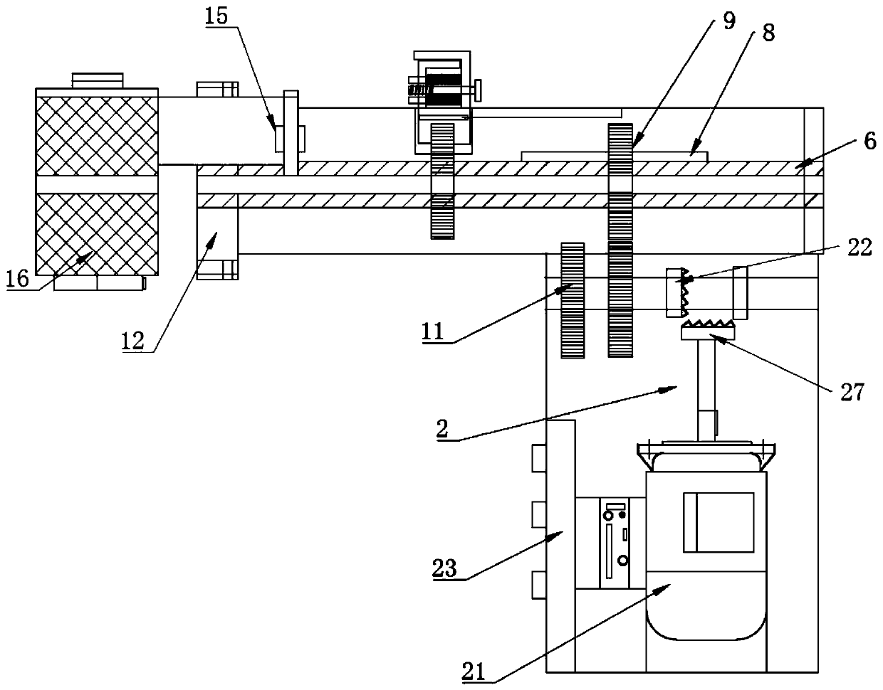
[0044] like Figure 1-Figure 7 As shown, a wire connection device for field wiring of electric power includes a bushing 1 and a power part 2, a sliding groove 3 is opened on the upper part of the bushing 1, and a clamping part 4 is slidably installed in the sliding groove 3, and the clamping part 4 The lower part is fitted with a sliding gear 10, and the end of the sliding groove 3 is provided with a ring groove 5 arranged around the center of the casing 1. The inside of the casing 1 is fitted with a rotating shaft 6, and the outside of the casing 1 is provided with a mounting hole. A thread clamping part is installed in the hole, and the thread clamping part is installed coincident with the center of the rotating shaft 6; a central hole is opened at the center of the rotating shaft 6, and a sliding key 8 is installed on the rotating shaft 6, and a fixed gear 9 is installed on the sliding key 8 With the sliding gear 10, the lower part of the sleeve with the feather key 8 is in...

Embodiment 2

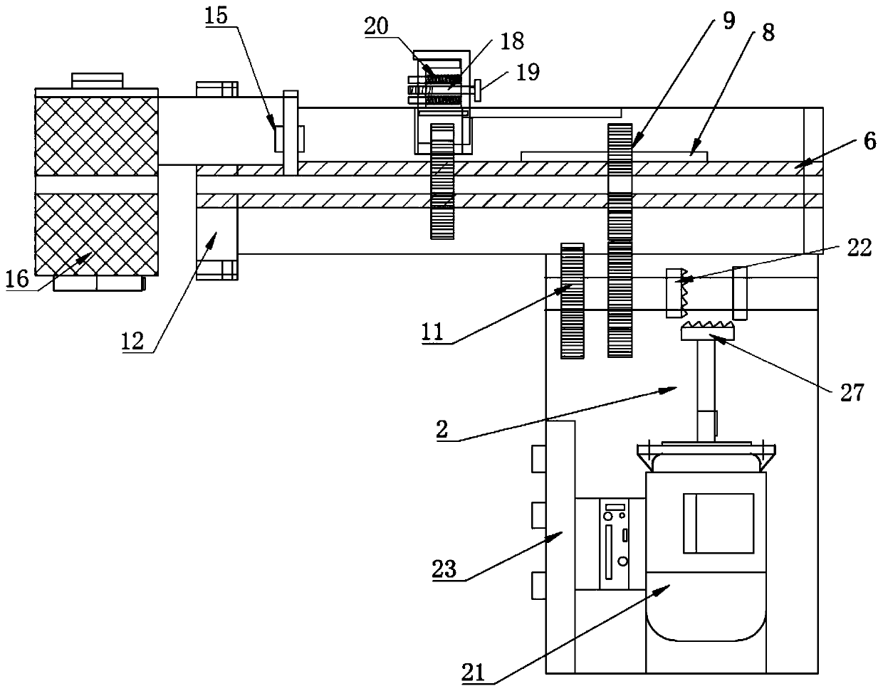
[0059] like Figure 8 As shown, the difference between this embodiment and Embodiment 1 lies in the following two aspects:

[0060] The clamping frames 7 are hinged, and the part of the adjusting column 18 set between the clamping frames 7 is set with a return spring; the clamping frame 7 has a simple structure and is easy to operate;

[0061] The power part 22 comprises a first sprocket 24 and a rotating handle 26, the sprocket is installed on the power shaft, the rotating handle 26 is equipped with a second sprocket 25 connected with the sprocket by a chain, and the outer diameter of the second sprocket 25 is larger than The outer diameter of the first sprocket 24; the first sprocket 24 and the second sprocket 25 are connected by a chain, and the large outer diameter of the second sprocket 25 can drive the power gear 11 to rotate more quickly, save energy, and can achieve connection role.

[0062] Using the above-mentioned technical scheme, the following are two actual cas...


PUM


Abstract

Disclosed is a lead connecting tool in particular to a conductor connecting device for electric power field wiring, including sleeves and power components, the upper part of the sleeve is provided with a sliding groove, a clamp is slidably mounted in the sliding groove, a lower portion of the clamping member is fitted with a sliding gear, a slide key is installed on the rotating shaft, a stationary gear and a sliding gear are arranged on that sliding key, the fixed gear and the lower part of the sliding gear are meshed and mounted with a power gear, a power gear is mounted on the power shaft,the edge of the bobbin is provided with a threading groove. The sleeve, the rotating shaft, the spool, the fixed gear and the sliding gear are all provided with placement grooves extending to the endportions, and the placement grooves of the fixed gear and the rotating shaft are arranged on corresponding positions, and the placement grooves of the sliding gears when the sliding gears are installed on the rotating shaft are different from the radial positions of the placement grooves of the fixed gears. The invention achieves the connection of wires with different diameters, widths and lengths, can save wires and cost, and can standardize nodes at the same time.

Description

technical field [0001] The invention relates to the technical field of wire connection tools, in particular to a wire connection device for electric field wiring. Background technique [0002] In the field of power wiring, the usual method of paralleling wires is to peel off the insulation of the wire ends first, and then take one of the wires as the central conductor, and wind the other wires on the central conductor. At present, the paralleling of the wires uses three Operation methods, specifically: [0003] The first method is manual paralleling, which will cause great harm to human hands during the process of paralleling. At the same time, the thread head is not firm after paralleling, and it is easy for wires to fall or drop out. The efficiency of paralleling is low; and it is easy to cause waste of wires; [0004] The second method: use tools such as pliers to bend the wire, it is easy to scratch the wire when bending the wire, and the gap between the bent coils is l...

Claims


Application Information

Patent Timeline
Patent Type & Authority Patents(China)
IPC IPC(8): H01R43/26H01R43/28H01R43/20
CPCH01R43/20H01R43/26H01R43/28
Inventor 赵延东宋怡曾乐宏王建宇成刚田玺温夏德任明立志王振海
Owner STATE GRID SHANDONG ELECTRIC POWER COMPANY WEIFANG POWER SUPPLY
Why Eureka
Try Eureka