Light guide plate assembling device

A technology for assembling device and light guide plate, which is applied in metal processing and other directions, and can solve the problems of large cutting size error, single function, low work efficiency, etc.

Inactive Publication Date: 2019-01-15
泉州睿骋企业管理咨询有限公司
View PDF4 Cites 0 Cited by
  • Summary
  • Abstract
  • Description
  • Claims
  • Application Information

AI Technical Summary

Problems solved by technology

[0002] When producing the light guide plate, it is necessary to cut the light guide plate. The current cutting equipment usually only has a one-way cutting function, and its function is single. During the cutting process, the direction of the light guide plate needs to be adjuste...

Method used


Image

  • Light guide plate assembling device
  • Light guide plate assembling device
  • Light guide plate assembling device

Examples


Embodiment Construction

[0015] Combine below Figure 1-4 The present invention will be described in detail.

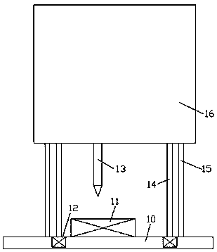
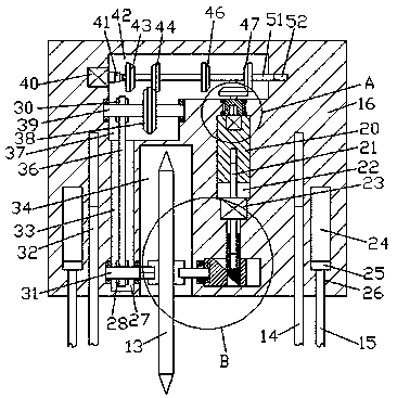
[0016] refer to Figure 1-4 , a light guide plate assembly device according to an embodiment of the present invention, comprising a main body 16 and a lifting assembly arranged on the lower side of the main body 16, the bottom end surface of the main body 16 is provided with a mounting hole 34, the installation A cutter 13 is arranged in the hole 34, and lugs 71 are fixed symmetrically to the center of the left and right sides of the cutter 13. The left side of the left side of the left side of the lug 71 is provided with a first spline cavity 75. The right end surface of the lug 71 on the side is provided with an insertion hole 76, and the first transmission cavity 33 is extended up and down in the main body 16 on the left side of the installation hole 34, and the lower side of the first transmission cavity 33 A first revolving pin shaft 31 is installed in a rotating fit, the outer surface...


PUM


Abstract

The invention discloses a light guide plate assembling device. The device comprises a main machine body, and a lifting assembly which is arranged at the lower side of the main machine body, wherein amounting hole in which a cutting tool is formed in the end surface of the bottom part of the main machine body; lugs are symmetrically fixedly arranged in the centers of the end surfaces of the left side and the right side of the cutting tool; a first spline chamber is formed in the end surface of the left side of the lug at the left side; an inserting hole is formed in the end surface of the right side of the lug at the right side; a first transmission chamber up and down extends in the main machine body at the left side of the mounting hole; a first rotating hinge pin is mounted at the lowerside of the first transmission chamber in a rotating fitting manner; a first transmission wheel is fixedly arranged on the outer surface of the first rotating hinge pin; the tail end of the right side of the first rotating hinge pin extends into the mounting hole and is fixedly equipped with a first spline shaft; the first spline shaft is connected to the first spline chamber in a spline fittingmanner; and a second transmission chamber communicates with the top wall of the first transmission chamber.

Description

technical field [0001] The invention relates to the technical field of light guide plate processing, in particular to a light guide plate assembly device. Background technique [0002] When producing the light guide plate, it is necessary to cut the light guide plate. The current cutting equipment usually only has a one-way cutting function, and its function is single. During the cutting process, the direction of the light guide plate needs to be adjusted manually, which is cumbersome to operate and low in efficiency. , Moreover, the cutting process of the light guide plate needs manual control operation, the cutting size error is large, and the replacement steps of the cutting knife are cumbersome, so it needs to be improved. Contents of the invention [0003] The object of the present invention is to provide a light guide plate assembly device for overcoming the above-mentioned defects in the prior art. [0004] A light guide plate assembly device according to the prese...

Claims


Application Information

Patent Timeline
IPC IPC(8): B26D1/18B26D5/06B26D5/08B26D7/26B26D7/24
CPCB26D1/185B26D5/06B26D5/086B26D7/24B26D7/2621B26D7/2635
Inventor 曾志华
Owner 泉州睿骋企业管理咨询有限公司
Why Eureka
Try Eureka