Cutting device

A technology of cutting device and cutting table, applied in metal processing and other directions, can solve the problems of low processing efficiency, lack of good limit protection, cumbersome operation process, etc., and achieve the effect of simple and reasonable installation structure

Pending Publication Date: 2019-01-25
YINGSHANG BOHAO PLASTIC IND TECH CO LTD
View PDF0 Cites 0 Cited by
  • Summary
  • Abstract
  • Description
  • Claims
  • Application Information

AI Technical Summary

Problems solved by technology

[0004] The purpose of the present invention is to provide a cutting device to solve the problem that the existing cutting device proposed in the above background technology usually cuts directly, does not have the function of good limit protection, and when the cutting force is too large, it will cause cutting The problem of deviation of incoming materials during the process, and the structure of the existing cutting device is relatively complicated, the operation process is relatively cumbersome, and the requirements for the skills of the staff are too high, resulting in the problem of relatively low processing efficiency

Method used


Image

  • Cutting device
  • Cutting device
  • Cutting device

Examples


Embodiment 1

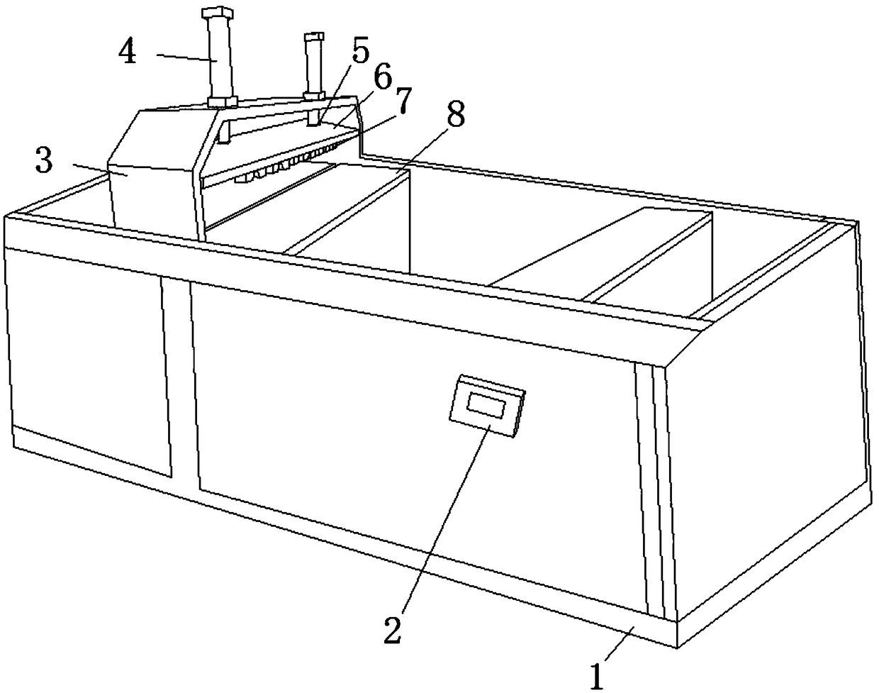
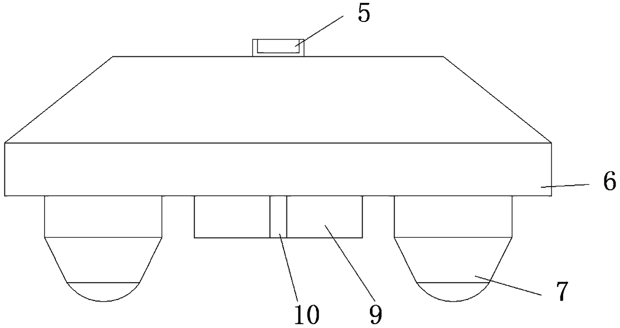
[0019] see Figure 1-3 , the present embodiment provides a cutting device, including a device main body 1, a control button 2 is embedded in one side of the device main body 1, and the control button 2 is connected with a hydraulic cylinder 4 and an electric control air cut-off oil cylinder 11 through a wire, and the device main body 1 A mounting frame 3 is provided on one side of the top of the hydraulic cylinder 4, and one end of the hydraulic cylinder 4 passing through the mounting frame 3 is connected with a locking member 5. The bottom of the locking member 5 is fixedly installed with a positioning platform 6, and the bottom of the positioning platform 6 is provided with a limit block 7. The center of the bottom of the positioning table 6 is embedded with a base 9, the middle part of the base 9 is provided with a knife groove 10, the lower part of the knife groove 10 is provided with a cutting table 8, and the inner center of the cutting table 8 is embedded with an electro...

Embodiment 2

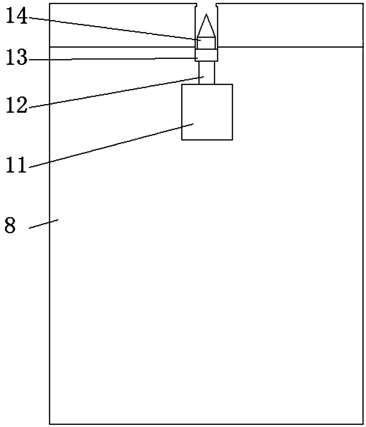
[0022] see Figure 1-3 , on the basis of Embodiment 1, a further improvement has been made: the side of the cutting table 8 close to the telescopic column 12 is provided with a knife edge, which is convenient for the rapid expansion and contraction of the knife 14. There are material guide grooves on both sides, and the material is placed on the top of the material guide table, and at the same time, the side is placed in the material guide groove for smooth movement and limit support.

[0023] Among them, there are four telescopic columns 12, which are convenient to be evenly arranged horizontally on the bottom of the tool mounting seat 13, so as to ensure uniform force and precise cutting. Matching, two-way limit support, positioning cutting, one side of the control button 2 is provided with a protective cover, external protection, to prevent accidental touch.


PUM


Abstract

The invention discloses a cutting device which comprises a device body. A control button is mounted on a side of the device body in an embedded manner and is connected with hydraulic cylinders and anelectric control gas shutoff oil cylinder by wires, a mounting frame is arranged on a side of the top of the device body, a locking component is connected with the end, which penetrates the mounting frame, of each hydraulic cylinder, a positioning table is fixedly mounted at the bottoms of the locking components, limit blocks are arranged at the bottom of the positioning table, a base is mounted in the center of the bottom of the positioning table in an embedded manner, and a cutter groove is formed in the middle of the base. The cutting device has the advantages that the problem of deviationof supplied materials in case of excessively high cutting force in cutting procedures due to the fact that the supplied materials are generally directly cut by existing cutting devices without good limit protection functions can be solved by the aid of the cutting device, and the problems of relatively low machining efficiency due to relatively complicated structures of the existing cutting devices, tedious operation procedures and excessively high skill requirements on staffs can be solved by the aid of the cutting device.

Description

technical field [0001] The invention relates to the technical field of cutting devices, in particular to a cutting device. Background technique [0002] PVC tile is made of polyvinyl chloride resin (referred to as PVC) as the main raw material, supplemented by UV anti-ultraviolet agent and other chemical raw materials. It is made of scientific proportion and advanced technology. PVC tile is also called plastic steel tile. The replacement product of the tile adopts multi-layer co-extrusion composite technology, and the anti-aging layer is covered on the surface of the product, which improves the weather resistance and color durability. The bottom surface adds a wear-resistant layer, which has good fire resistance, corrosion resistance and weather resistance. , does not contain asbestos components, bright colors, environmentally friendly and healthy, and is widely used in the roof and wall of large-span portal structure factories. It not only meets the anti-corrosion requireme...

Claims


Application Information

Patent Timeline
Patent Type & Authority Applications(China)
IPC IPC(8): B26D1/08B26D7/01
CPCB26D1/08B26D7/01
Inventor 胡强
Owner YINGSHANG BOHAO PLASTIC IND TECH CO LTD
Why Eureka
Try Eureka