Frame structure of aerial photograph unmanned aerial vehicle

A frame structure and UAV technology, applied in the field of UAVs, can solve problems such as flight interference and low frame functionality, and achieve the effect of being vulnerable to damage

Inactive Publication Date: 2018-11-13
NANJING HANXIYUE AUTOMATION TECH CO LTD
View PDF0 Cites 0 Cited by
  • Summary
  • Abstract
  • Description
  • Claims
  • Application Information

AI Technical Summary

Problems solved by technology

[0003] The purpose of the present invention is to provide a rack structure for aerial photography UAVs to solve the problem that the existing racks proposed in the above background technology have low functionality and are likely to cause interference to flight

Method used


Image

  • Frame structure of aerial photograph unmanned aerial vehicle
  • Frame structure of aerial photograph unmanned aerial vehicle
  • Frame structure of aerial photograph unmanned aerial vehicle

Examples


Embodiment 1

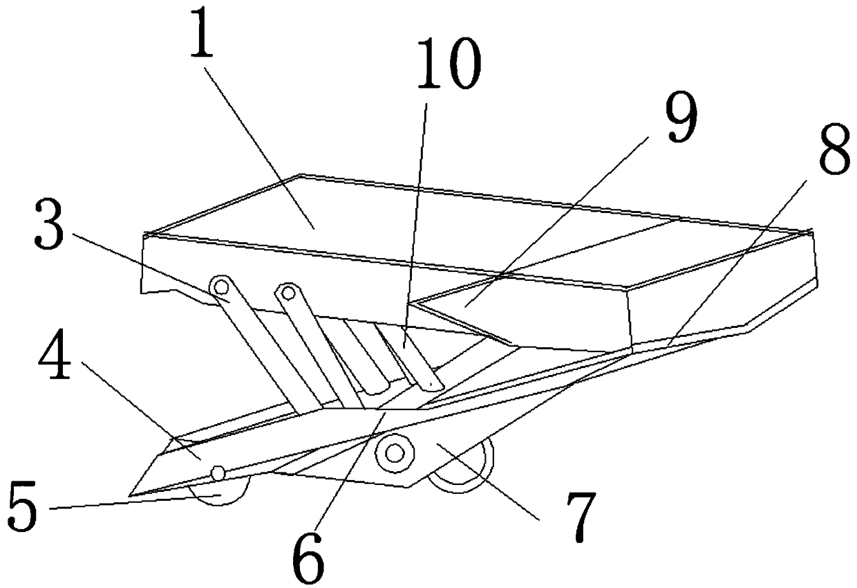
[0020] see figure 1 and figure 2 , the present embodiment provides a frame structure of an aerial photography drone, including a frame 4 and an installation platform 1, the frame 4 is located at the lower end of the installation platform 1, and one side of the frame 4 is connected to the installation platform 1. The outer sidewalls are hinged to each other, and a pin shaft 8 is installed at the hinge between the frame 4 and the mounting stage 1, and a spring is installed on the outer edge of the pin shaft 8, and the spring is connected with the frame 4 and the mounting stage 1 respectively, and the mounting stage 1 A guide frame 9 is fixedly installed on one side of the outer wall, and a guide groove 6 is provided on one side of the outer wall of the frame 4. There are gas springs 10 fixedly connected between them, two gas springs 10 are provided, and the frame 4 is connected with the side wall of the mounting platform 1 through the folding frame 3, and the folding frame 3 i...

Embodiment 2

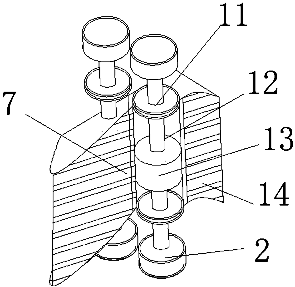
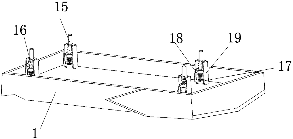
[0023] see image 3 , on the basis of Embodiment 1, a further improvement has been made: the upper end surface of the mounting platform 1 is fixedly installed with a bearing seat 19, the upper end of the bearing seat 19 is slidably connected with a bearing column 15, and the middle part of the inner cavity of the bearing seat 19 is provided with a connecting bolt 16, the connecting bolt 16 is fixedly connected with the bearing column 15, the lower end of the connecting bolt 16 is fixedly equipped with a spring 18, the bottom of the spring 18 is fixedly connected with a support shaft 17, and the support shaft 17 is fixedly connected with the end face of the frame 4.

[0024] Wherein, bearing base 19 is the fixed installation structure that is used for installing on the carrier platform 1, and it is mainly responsible for installing the camera and the installation of related components on the carrier platform 1, on this platform, bearing base 19 can be provided with a plurality o...


PUM


Abstract

The invention discloses a frame structure of an aerial photograph unmanned aerial vehicle. The frame structure of the aerial photograph of unmanned aerial vehicle comprises a frame and a mounting platform, wherein the frame is positioned at the lower end of the mounting platform, one side of the frame is hinged to the outer side wall of the mounting platform mutually, and gas springs are fixedly connected between the upper end face of the frame and the lower end face of the mounting platform. A guide block is fixedly mounted on the lower end face of the frame, a limiting block is fixedly connected to one side of the guide block, and a limiting groove is formed between the guide block and the limiting block, a mounting shaft is arranged in the limiting groove, a driving motor is rotationally connected with the middle part of the mounting shaft, the driving motor is fixedly connected with the inner wall of the limiting groove, and bottomed wheels are fixedly connected to both ends of themounting shaft. The frame structure of the aerial photograph unmanned aerial vehicle overcomes defects of an existing frame and prolongs the service life of an unmanned aerial vehicle.

Description

technical field [0001] The invention relates to the technical field of unmanned aerial vehicles, in particular to a frame structure of an aerial photography unmanned aerial vehicle. Background technique [0002] The drone chassis is a bracket installed at the bottom of the drone to support the drone. It can provide effective protection for the drone when it takes off and lands, and the support is convenient for the drone to take off and land. However, the traditional UAV base frame is a simple support frame structure, which is not only easy to bend and break when it is hit by a strong impact, but also has a single function and does not have other multi-functionality. Some chassis will also affect the flight stability of the UAV, thereby affecting the aerial photography effect, so it needs to be improved. Contents of the invention [0003] The purpose of the present invention is to provide a frame structure of an aerial photography UAV, so as to solve the problem of low fu...

Claims


Application Information

Patent Timeline
Patent Type & Authority Applications(China)
IPC IPC(8): B64D47/08B64D45/00
CPCB64D45/00B64D47/08B64U2101/30
Inventor 李馨嫔
Owner NANJING HANXIYUE AUTOMATION TECH CO LTD
Why Eureka
Try Eureka