Ultra-thin non-rubber-coating copper plate and production method thereof

A production method and technology of copper clad laminates, applied in metal processing and other directions, can solve the problems of cumbersome operation, large cutting size error, single function, etc., and achieve the effect of simple and efficient replacement operation

Inactive Publication Date: 2019-01-18
福建泉州远方致远自动化科技有限公司
View PDF0 Cites 0 Cited by
  • Summary
  • Abstract
  • Description
  • Claims
  • Application Information

AI Technical Summary

Problems solved by technology

[0002] When producing adhesive-free copper-clad laminates, it is necessary to cut and process the adhesive-free copper-clad laminates. The current cutting equipment usually only has a one-way cutting function, and its function is single. It is necessary to manually adjust the direction of the adhesive-free copper-clad laminates during cutting. The operation is cumbersome and the work efficiency is low. Moreover, the cutting process of the glueless copper clad laminate requires manual control operation, the cutting size error is large, and the replacement steps of the rotating cutter body are cumbersome. Therefore, it needs to be improved.

Method used


Image

  • Ultra-thin non-rubber-coating copper plate and production method thereof
  • Ultra-thin non-rubber-coating copper plate and production method thereof
  • Ultra-thin non-rubber-coating copper plate and production method thereof

Examples


Embodiment Construction

[0015] Combine below Figure 1-4 The present invention will be described in detail.

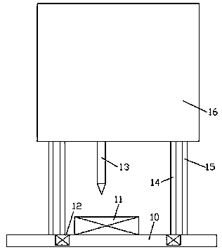
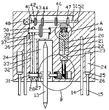
[0016] refer to Figure 1-4 , an ultra-thin adhesive-free copper-clad laminate and a manufacturing method thereof according to an embodiment of the present invention, which uses an ultra-thin adhesive-free copper-clad laminate equipment, and the ultra-thin adhesive-free copper-clad laminate equipment includes a processing seat 16 and a set The lifting element on the lower side of the processing seat 16, the bottom end surface of the processing seat 16 is provided with an assembly groove 34, and a rotating cutter body 13 is arranged in the assembly groove 34, and the left and right sides of the rotating cutter body 13 are positive A convex handle 71 is fixed symmetrically in the center, a first spline cavity 75 is provided in the left end surface of the convex handle 71 on the left side, and an insertion cavity 76 is provided in the right end surface of the right convex handle 71, so The pro...


PUM


Abstract

The invention discloses an ultra-thin non-rubber-coating copper plate and a production method thereof. Ultra-thin non-rubber-coating copper plate equipment is used, the ultra-thin non-rubber-coating copper plate equipment comprises a processing seat and a lifting and lowering member which is arranged on the lower side of the processing seat, an assembly groove is formed in the bottom end face of the processing seat, a rotary cutter body is arranged in the assembly groove, protruded handles are symmetrically and fixedly arranged on the centers of the both left and right side end faces of the rotary cutter body, a first spline cavity is formed in the left side end face of the protruded handle on the left side, an inserting cavity is formed in the right side end face of the protruded handle on the right side, a first delivery cavity extending up and down is formed in the processing seat located on the left side of the assembly groove, a first rotary rod is rotatably and cooperatively installed on the lower side of a first delivery cavity, a first delivery wheel is fixedly arranged on the outer surface of the first rotary rod, the rear end of the right side of the first rotary rod extends to the assembly groove to be fixedly provided with a first spline shaft, the first spline shaft is in spline cooperative connection with the first spline cavity, and a second delivery cavity is communicated with the top wall of the first delivery cavity.

Description

technical field [0001] The invention relates to the technical field of glue-free copper-clad laminate processing, in particular to an ultra-thin glue-free copper-clad laminate and a manufacturing method thereof. Background technique [0002] When producing adhesive-free copper-clad laminates, it is necessary to cut and process the adhesive-free copper-clad laminates. The current cutting equipment usually only has a one-way cutting function, and its function is single. It is necessary to manually adjust the direction of the adhesive-free copper-clad laminates during cutting. The operation is cumbersome and the work efficiency is low. Moreover, the cutting process of the glueless copper-clad laminate requires manual control operation, the cutting size error is large, and the replacement steps of the rotating cutter body are cumbersome. Therefore, it needs to be improved. Contents of the invention [0003] The object of the present invention is to provide an ultra-thin adhesi...

Claims


Application Information

Patent Timeline
Patent Type & Authority Applications(China)
IPC IPC(8): B26D1/18B26D7/26
CPCB26D1/18B26D7/2614B26D7/2635
Inventor 曾志华曾明华
Owner 福建泉州远方致远自动化科技有限公司
Why Eureka
Try Eureka