Automatic angle adjusting device for rear-view mirror of cart

An automatic adjustment, rear-view mirror technology, used in optical observation devices, vehicle components, transportation and packaging, etc., can solve problems such as inner wheel difference blind spots, and achieve the effect of eliminating visual blind spots.

Active Publication Date: 2019-01-15
盐城柏达电气科技有限公司
View PDF6 Cites 1 Cited by
  • Summary
  • Abstract
  • Description
  • Claims
  • Application Information

AI Technical Summary

Problems solved by technology

[0003] The invention provides an automatic adjustment device for the rearview mirror angle of a large vehicle, so as to solve the problem in the prior art that there is a blind area of ​​the inner wheel difference when turning

Method used


Image

  • Automatic angle adjusting device for rear-view mirror of cart
  • Automatic angle adjusting device for rear-view mirror of cart
  • Automatic angle adjusting device for rear-view mirror of cart

Examples


Embodiment Construction

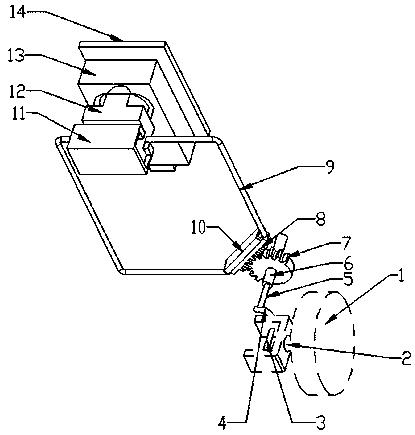
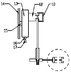
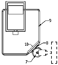
[0019] Such as figure 1 , figure 2 , image 3 , Figure 4 , Figure 5 , Image 6 , Figure 7 , Figure 8 with Figure 9 As shown, a rearview mirror angle automatic adjustment device for a large vehicle is composed of a steering knuckle arm 4, a spline shaft 5, a spline sleeve 6, a sector gear 7, a rack 8, a cable 9, a rack guide rail 10, and a driving cam Guide rail 11, rearview mirror active cam 12, rearview mirror driven cam 13, rearview mirror 14 and fixed bracket 17, the steering knuckle arm 4 is connected to the steering knuckle 2 through the kingpin 3, and the steering knuckle 2 is connected to the tire 1 , the spline shaft 5 is fixed on the steering knuckle arm 4, the rack guide rail 10 is fixed on the vehicle body, the rearview mirror 14 is connected to the vehicle body through a fixed bracket 17, and the rear part of the rearview mirror 14 is connected to the rear through a ball joint 15 The mirror driven cam 13 is connected, the active cam guide rail 11 is f...


PUM


Abstract

An automatic angle adjusting device for a rear-view mirror of a cart is provided. While the steering knuckle arm drives the steering knuckle to rotate around the kingpin to drive the steering wheel torotate, a spline shaft mounted on steering knuckle arm, a spline sleeve and the sector gear also rotate with the steering knuckle arm, and the sector gear drives the rack to move to the left or right, thereby pulling the cable to move, pulling the mirror driving cam to move along the driving cam guide rail, pushing the mirror driven cam to rotate along the ball joint connected with the fixed bracket, and driving the mirror to rotate. The device adopts a sector gear, a rack and a driving cam driven by a steering knuckle arm in an automobile steering mechanism, and an automatic angle adjustingdevice of a rear-view mirror of a large vehicle composed of a driven cam part, thereby realizing that the reflection angle of the rear-view mirror rotates simultaneously with the rotation of a steering wheel, thereby eliminating the visual blind area caused by the inner wheel difference when steering.

Description

technical field [0001] The invention relates to the technical field of vehicle driving safety, in particular to a device for automatically adjusting the angle of rearview mirrors of large vehicles. Background technique [0002] Due to the existence of the inner wheel difference of the vehicle, when the vehicle is turning, the trajectories of the front and rear wheels do not coincide, resulting in a blind area of ​​the inner wheel difference. The longer the vehicle body, the larger the area of ​​the blind area. The front part of the car passed through when turning, but the middle and rear parts of the vehicle did not pass, and the traffic accidents caused increased year by year, especially large trucks and buses. Small and medium-sized vehicles have relatively small areas of blind spots in the inner wheel differential, and fewer traffic accidents occur. Therefore, how to eliminate the blind spots caused by the inner wheel difference when turning large vehicles has become a k...

Claims


Application Information

Patent Timeline
Patent Type & Authority Applications(China)
IPC IPC(8): B60R1/06
CPCB60R1/061B60R1/064
Inventor 张文张孝菲李华王学军李凤芹张梦茜
Owner 盐城柏达电气科技有限公司
Why Eureka
Try Eureka