drying rack for textiles

A technology for drying racks and textiles, applied in the field of drying racks, can solve the problems of lack of rain shielding equipment, inability to adjust the drying angle, and inability to adjust the drying length.

Inactive Publication Date: 2021-03-02
叶文娣
View PDF4 Cites 0 Cited by
  • Summary
  • Abstract
  • Description
  • Claims
  • Application Information

AI Technical Summary

Problems solved by technology

[0003] In order to overcome the shortcomings of ordinary drying devices that cannot adjust the drying length, need to bring their own clips, cannot adjust the drying angle, and have no rain-shielding equipment, the purpose of the present invention is to provide an adjustable drying length, which can fix the drying of textiles, and can be adjusted. Drying rack for textiles with rain protection equipment at drying angle

Method used


Image

  • drying rack for textiles
  • drying rack for textiles
  • drying rack for textiles

Examples


Embodiment 1

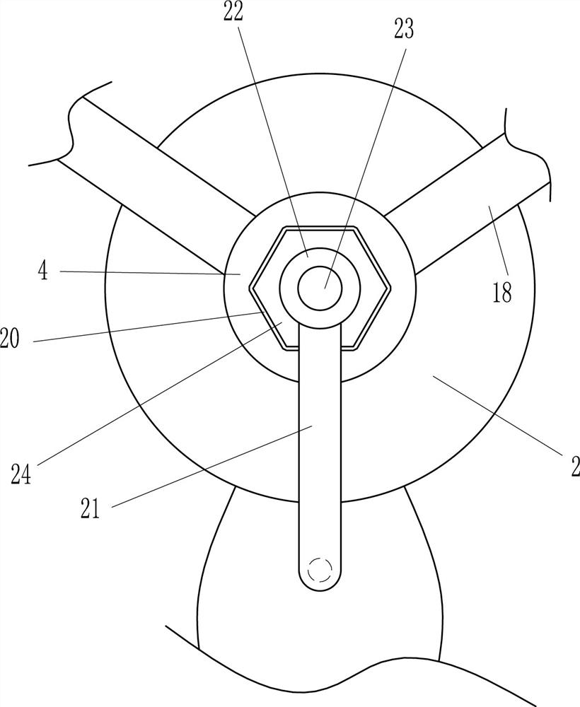
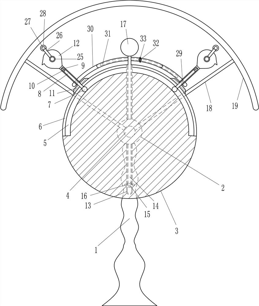
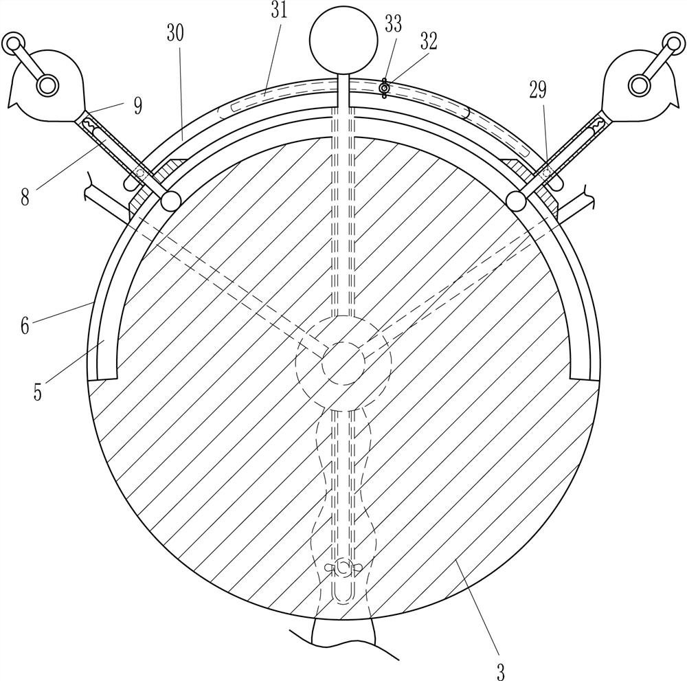
[0019] A textile drying rack, such as Figure 1-3 As shown, it includes a bracket 1, a bearing seat 2, a disc 3, a rotating shaft 4, a roller 7, an insertion rod 8, a hollow rod 9, a spring 10, a pressure plate 11, a cylinder 12, a lifting rod 14, a first bolt 15, The first wing nut 16 and the cylinder 17, the top of the bracket 1 is provided with a bearing seat 2, the front side of the bearing seat 2 is provided with a disc 3, the bearing seat 2 is provided with a rotating shaft 4, and the front end of the rotating shaft 4 is in contact with the rear side of the disc 3 , the rear end of the rotating shaft 4 passes through the bearing seat 2, the top of the disc 3 has a first arc-shaped hole 6, and the disc 3 at the bottom of the first arc-shaped hole 6 has a wheel groove 5, and the left and right sides of the wheel groove 5 The sliding type is provided with a roller 7, the top of the roller 7 is provided with an insertion rod 8, the top of the insertion rod 8 passes through t...

Embodiment 2

[0021] A textile drying rack, such as Figure 1-3 As shown, it includes a bracket 1, a bearing seat 2, a disc 3, a rotating shaft 4, a roller 7, an insertion rod 8, a hollow rod 9, a spring 10, a pressure plate 11, a cylinder 12, a lifting rod 14, a first bolt 15, The first wing nut 16 and the cylinder 17, the top of the bracket 1 is provided with a bearing seat 2, the front side of the bearing seat 2 is provided with a disc 3, the bearing seat 2 is provided with a rotating shaft 4, and the front end of the rotating shaft 4 is in contact with the rear side of the disc 3 , the rear end of the rotating shaft 4 passes through the bearing seat 2, the top of the disc 3 has a first arc-shaped hole 6, and the disc 3 at the bottom of the first arc-shaped hole 6 has a wheel groove 5, and the left and right sides of the wheel groove 5 The sliding type is provided with a roller 7, the top of the roller 7 is provided with an insertion rod 8, the top of the insertion rod 8 passes through t...

Embodiment 3

[0024] A textile drying rack, such as Figure 1-3 As shown, it includes a bracket 1, a bearing seat 2, a disc 3, a rotating shaft 4, a roller 7, an insertion rod 8, a hollow rod 9, a spring 10, a pressure plate 11, a cylinder 12, a lifting rod 14, a first bolt 15, The first wing nut 16 and the cylinder 17, the top of the bracket 1 is provided with a bearing seat 2, the front side of the bearing seat 2 is provided with a disc 3, the bearing seat 2 is provided with a rotating shaft 4, and the front end of the rotating shaft 4 is in contact with the rear side of the disc 3 , the rear end of the rotating shaft 4 passes through the bearing seat 2, the top of the disc 3 has a first arc-shaped hole 6, and the disc 3 at the bottom of the first arc-shaped hole 6 has a wheel groove 5, and the left and right sides of the wheel groove 5 The sliding type is provided with a roller 7, the top of the roller 7 is provided with an insertion rod 8, the top of the insertion rod 8 passes through t...


PUM


Abstract

The invention relates to a drying rack, in particular to a textile drying rack. The object of the present invention is to provide a textile drying rack with adjustable drying length, fixed drying textile, adjustable drying angle and rain-shielding equipment. The technical solution is: a textile drying rack, including a bracket, a bearing seat, a disc, a rotating shaft, a roller, an insertion rod, a hollow rod, a spring, a pressure plate, a cylinder, a lifting rod, a first bolt, etc.; The bearing seat is provided with a disc on the front side of the bearing seat, and a rotating shaft is arranged on the bearing seat. The front end of the rotating shaft contacts the rear side of the disc, and the rear end of the rotating shaft passes through the bearing seat. A wheel groove is arranged on the disc at the bottom of the shaped hole. In the present invention, the distance between the left and right cylinders can be adjusted according to the length of the textile through the insertion rod, so that the textile can be unfolded; the insertion rod can be fixed without moving by setting the pressure plate; Textiles can be fixed so they won't be blown away by the wind.

Description

technical field [0001] The invention relates to a drying rack, in particular to a textile drying rack. Background technique [0002] When people need to dry textiles, people generally dry the textiles on a rope or a pole, but when the textiles are long, common drying equipment cannot extend the pole or rope, which is inconvenient for people. Fully dry the textiles. In order not to blow the textiles away by the wind, people will bring their own clips to clamp and fix the textiles, and the sun position will change with time. The ordinary drying device cannot adjust the angle of the textiles. And people need to pay close attention to the change of weather all the time, once run into rainy day, people must rush to the drying place and textiles are put away, prevent textiles from being drenched. Contents of the invention [0003] In order to overcome the shortcomings of ordinary drying devices that cannot adjust the drying length, need to bring their own clips, cannot adjust t...

Claims


Application Information

Patent Timeline
Patent Type & Authority Patents(China)
IPC IPC(8): D06F57/08
CPCD06F57/08
Inventor 雷群叶文娣
Owner 叶文娣
Why Eureka
Try Eureka