Blowout preventer
A blowout preventer and casing technology, which is applied in the field of anti-leakage equipment, can solve the problems of inconvenient operation and high sealing requirements at the connection of the air pump, and achieve the effects of easy operation, prevention of blowout accidents, and increased sealing effect
- Summary
- Abstract
- Description
- Claims
- Application Information
AI Technical Summary
Problems solved by technology
Method used
Image

Examples
Embodiment 1
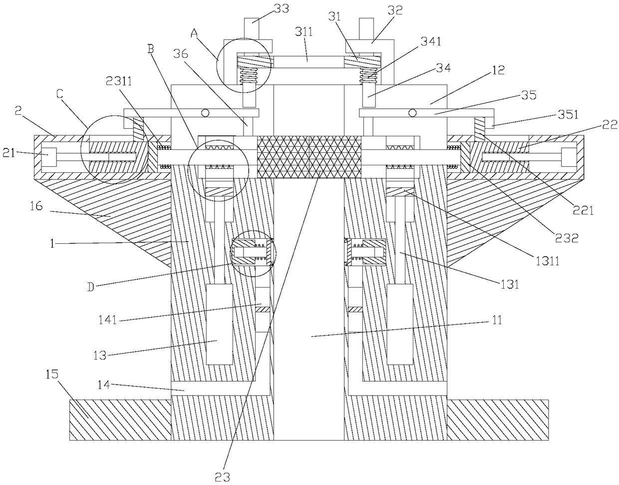
[0029] like Figure 1-7As shown, a blowout preventer includes a housing 1, a fixing plate 15 arranged on both sides of the housing 1 and a first equipment box 2 arranged above the fixing plate 15, the first equipment box 2 There are two groups, which are respectively fixed on both sides of the casing 1. The fixing plate 15 is used to fix the blowout preventer on the wellhead so that the blowout preventer can seal the oil well; the casing 1 is provided with a first channel hole 11, the oil delivery pipe can be inserted into the oil well from the first through hole to carry out oil pumping work; the first equipment box 2 is provided with a sealing assembly and a driving member for driving the sealing assembly to move; the first equipment The bottom of the box 2 is provided with a support seat 16; the support seat 16 is set as a triangular structure, and the first equipment box is fixed on the side wall of the housing by using the principle of triangular stability; the sealing as...
Embodiment 2
[0041] like Figure 8-10 As shown, the difference between this embodiment and Embodiment 1 is that: the fixing plate 15 is provided with a fixing device, and the fixing device is detachably connected with the fixing plate 15; the blowout preventer is fixed by the fixing device, increasing The fixing effect of the blowout preventer enables the blowout preventer to be fixed more stably at the wellhead and has a good blowout prevention effect; through the detachable connection between the fixing device and the fixing plate, the fixing device can be easily repaired and maintained, and the fixing time can be extended. The service life of the device.
[0042] Described fixing device comprises the second equipment box 4 that is located on described fixed plate 15, is located at the hydraulic cylinder 41 in described second equipment box 4, is located at the rotary motor 44 on the piston rod of described hydraulic cylinder 41 and The positioning drill bit 45 arranged on the output sh...
Embodiment 3
[0046] like Figure 11-12 As shown, the difference between this embodiment and Embodiment 1 is that a fixing assembly is also provided on the inner wall of the first through hole 11; the oil delivery pipe inserted into the blowout preventer is fixed by the fixing assembly, so as to prevent the oil delivery pipe from The vibration will affect the connection effect between the oil pipeline and the blowout preventer, improve the sealing performance of the blowout preventer, and avoid the occurrence of blowout accidents.
[0047] The fixing assembly includes a second mounting plate 5 disposed on the inner wall of the first through hole 11 , a connecting spring 54 disposed on the second mounting plate 5 , and a fastener fastened to the connecting spring 54 . Plate 51; two sets of fixing components are respectively installed on both sides of the inner wall of the first through hole. After the oil delivery pipe is inserted into the first through hole, the oil delivery pipe is placed ...
PUM
 Abstract
Description
Claims
Application Information
 - R&D
- Intellectual Property
- Life Sciences
- Materials
- Tech Scout
- Unparalleled Data Quality
- Higher Quality Content
- 60% Fewer Hallucinations
Browse by: Latest US Patents, China's latest patents, Technical Efficacy Thesaurus, Application Domain, Technology Topic, Popular Technical Reports.
© 2025 PatSnap. All rights reserved.Legal|Privacy policy|Modern Slavery Act Transparency Statement|Sitemap|About US| Contact US: help@patsnap.com