Low-noise vortex fuel pump

A fuel pump, low noise technology, applied in the field of vortex fuel pump, can solve the problems of large noise, strong mutual impact, large pressure pulsation of the fuel pump, etc., to achieve the effect of reducing noise and alleviating interference

Pending Publication Date: 2019-01-15
ZHEJIANG SHUANGLIANG AUTOMOBILE PARTS
View PDF0 Cites 0 Cited by
  • Summary
  • Abstract
  • Description
  • Claims
  • Application Information

AI Technical Summary

Problems solved by technology

[0003] Restricted by the manufacturing process, conventional fuel pump blades are mostly straight blades, which makes the interaction between the longitudinal vort

Method used


Image

  • Low-noise vortex fuel pump
  • Low-noise vortex fuel pump
  • Low-noise vortex fuel pump

Examples


Example Embodiment

[0028] Example 1

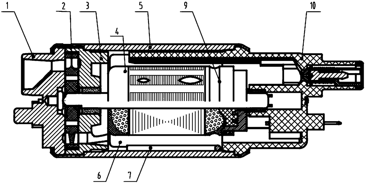
[0029] like figure 1 As shown, a low-noise vortex fuel pump includes a fuel pump body and an oil intake assembly arranged at the oil inlet end of the fuel pump body, wherein the oil intake assembly includes a pump cover 1, an impeller 2 and an impeller seat 3 arranged in sequence from outside to inside ;

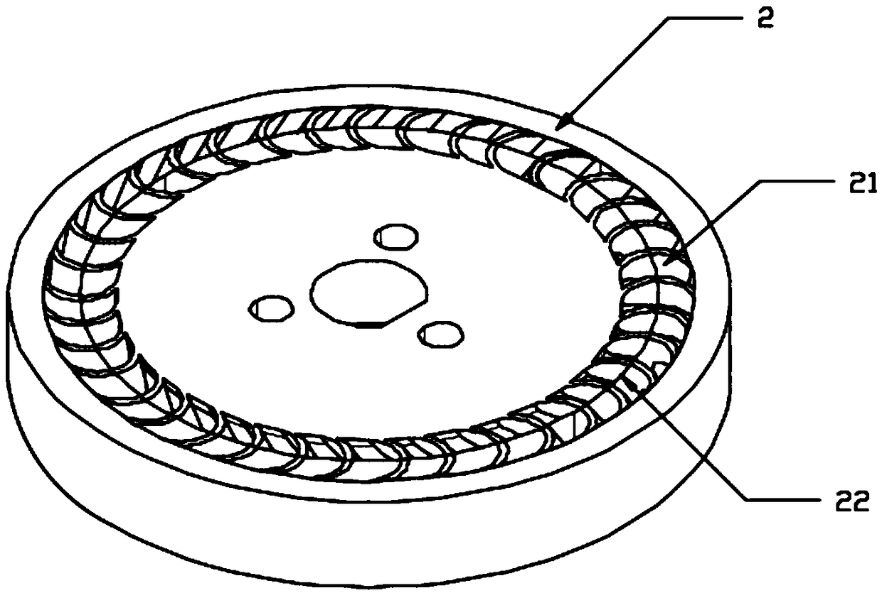
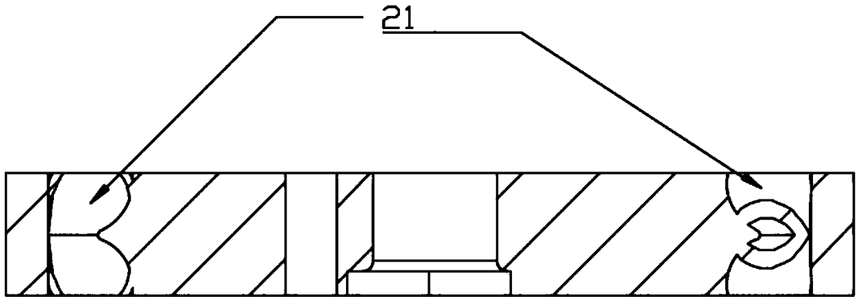
[0030] like figure 2 and image 3 As shown, the upper and lower end surfaces of the impeller 2 are oppositely provided with a plurality of arc-shaped blade groups 21. The arc-shaped blade group 21 includes an arc-shaped upper blade and a lower blade. The lower edge of the upper blade and the upper edge of the lower blade Fixed connection, the adjacent arc-shaped blade groups 21 form two arc-shaped channels in opposite directions, the fluid flows from the pump cover 1 through the arc-shaped channels on the impeller 2, and the interference is alleviated, and finally enters through the impeller seat. in the fuel pump body.

[0031] like figure 2 As sh...


PUM


Abstract

The invention discloses a low-noise vortex fuel pump comprising a fuel pump body and an oil inlet assembly disposed at an oil inlet end of the fuel pump body. The oil inlet assembly comprises a pump cover, an impeller and an impeller seat which are arranged in order from the outside to the inside. Upper and lower end surfaces of the impeller are oppositely provided with a plurality of arc-shaped blade sets. The arc-shaped blade sets comprise arc-shaped upper blades and arc-shaped lower blades. Lower edges of the upper blades are fixedly connected to upper edges of the lower blades. Two vertically arc-shaped channels in opposite directions are formed between the adjacent arc-shaped blade sets. A fluid flows from the pump cover through the arc-shaped channels on the impeller, and finally enters the fuel pump body through the impeller seat. Through arranging the plurality of vertically symmetrical arc-shaped blade sets on the impeller, an oil duct in the impeller is folded into the two vertically arc-shaped channels in the opposite directions, the interference of the fluid in the fuel pump can be alleviated, and the noise of the fuel pump can be significantly reduced.

Description

technical field [0001] The invention relates to a vortex fuel pump, in particular to a low-noise vortex fuel pump. Background technique [0002] Most of the existing fuel pumps for vehicles are vortex fuel pumps, which are characterized by small volume and high pressure. There is a longitudinal vortex on both sides of the impeller in the fuel pump and in the oil inlet and outlet passages, and the longitudinal vortex moves along the direction of impeller rotation. The longitudinal vortex of the fluid in the fuel pump enters and exits the impeller many times, gets work from the blades, and exchanges momentum with the fluid in the static flow channel, thereby obtaining the effect of pressure rise of the fluid in the pump. [0003] Restricted by the manufacturing process, conventional fuel pump blades are mostly straight blades, which makes the interaction between the longitudinal vortex and the blades, pump cover and flow channel of the pump body relatively strong, resulting i...

Claims


Application Information

Patent Timeline
IPC IPC(8): F02M37/04F04D29/22F04D29/24F04D29/66
CPCF02M37/04F04D29/2222F04D29/242F04D29/669
Inventor 张辉平
Owner ZHEJIANG SHUANGLIANG AUTOMOBILE PARTS
Why Eureka
Try Eureka