Wireless Communication with Suppression of Inter-Cell Interference in Large-Scale Antenna Systems

Active Publication Date: 2015-12-31
ALCATEL LUCENT SAS
View PDF9 Cites 5 Cited by
  • Summary
  • Abstract
  • Description
  • Claims
  • Application Information

AI Technical Summary

Benefits of technology

[0023]In further embodiments, the base station further comprises a module adapted to linearly combine signals received on the reverse link by said base station with signals

Problems solved by technology

The number of available orthogonal pilot sequences, however, is relatively small, and can be no more than the ratio of the coherence time to the delay spread.
This reuse of pilot sequences in diff

Method used


Image

  • Wireless Communication with Suppression of Inter-Cell Interference in Large-Scale Antenna Systems
  • Wireless Communication with Suppression of Inter-Cell Interference in Large-Scale Antenna Systems
  • Wireless Communication with Suppression of Inter-Cell Interference in Large-Scale Antenna Systems

Examples


Example

[0029]A message-carrying signal transmitted from a base station antenna array (downlink) or from a terminal antenna (uplink) during one channel use interval is referred to here as a “symbol”. A symbol is distributed in space and frequency, because each base station has multiple antennas for transmission / reception, and because each symbol will typically be distributed over multiple OFDM (orthogonal frequency-division multiplexing) subcarriers or “tones”.

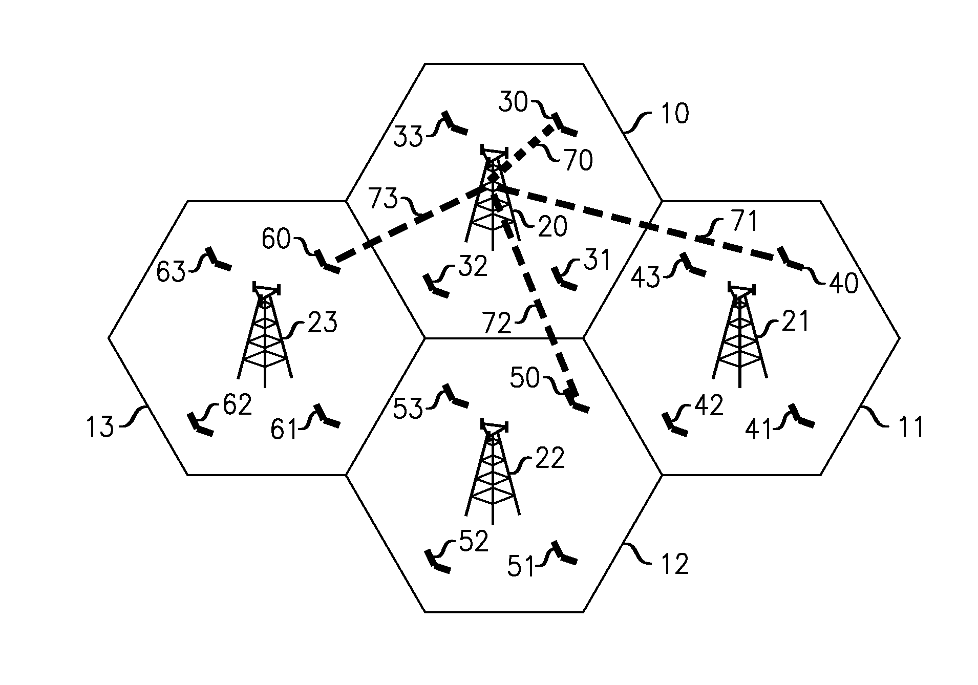
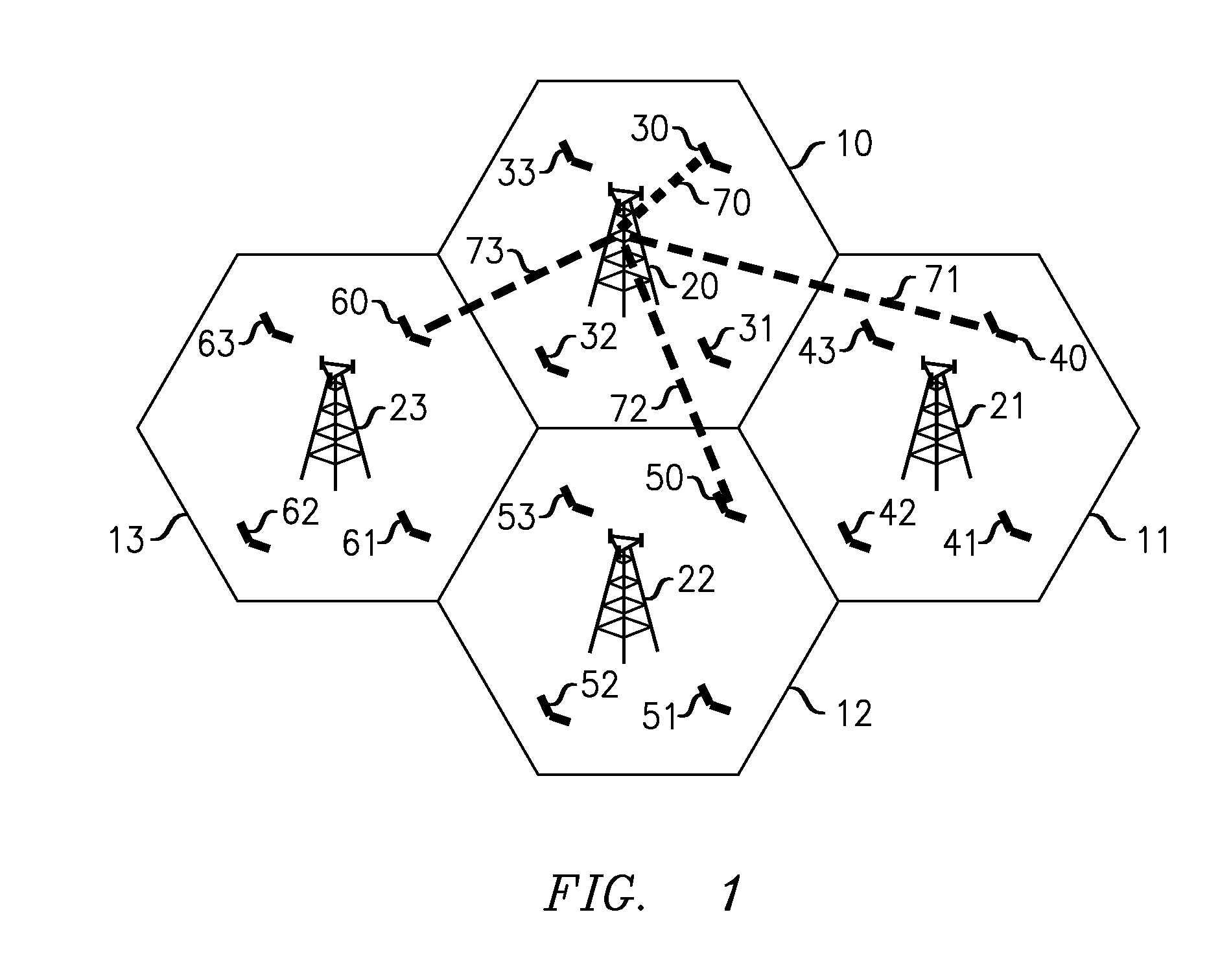
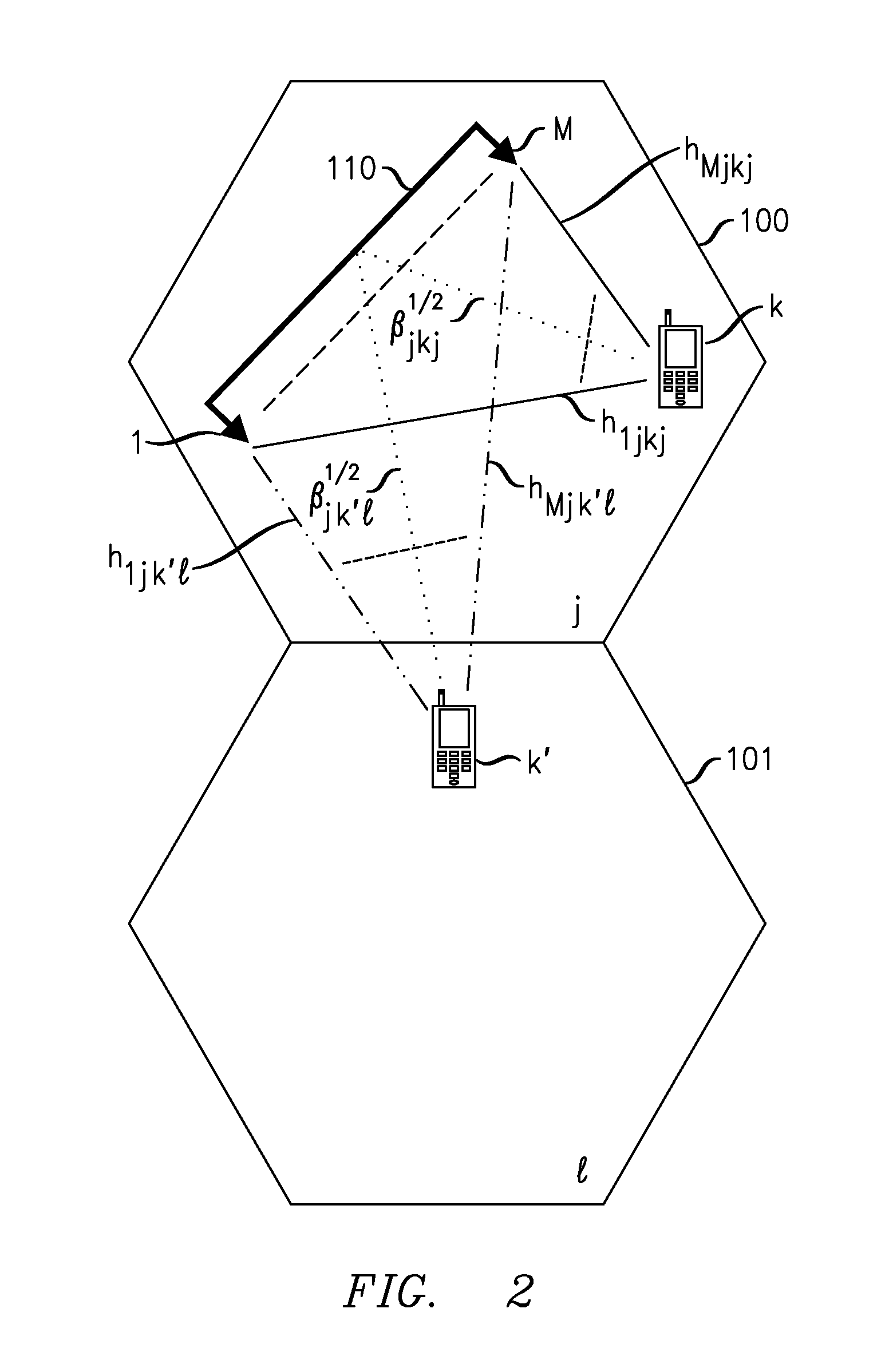
[0030]Unless specifically referred to as a terminal antenna, the term “antenna” refers to a base station antenna associated with a cell. Each cell has at most M antennas. The term “terminal” refers to a mobile user terminal.

[0031]The total number of cells in the wireless network is L. Each cell contains at most K terminals. The total number of pilot signals is K. The pilot signals are numbered 1, . . . , K. The pilot signals are assumed to be allocated to terminals such that, in each cell, the k-th terminal is allocated pilot signal k...


PUM


Abstract

In exemplary LSAS (large-scale antenna system) networks, uplink signals are processed to compensate for pilot contamination. Slow-fading coefficients are generated for terminals in the wireless network, and postcoding matrices are generated based on the slow-fading coefficients and terminal transmit power levels. Uplink signals are received from the terminals, and M-dimensional postcoding is performed to generate estimated uplink signals from the received uplink signals, where M is the number of antennas at a base station of the wireless network. The postcoding matrices are applied to the estimated uplink signals to compensate for pilot contamination. The improved technique used to generate postcoding matrices depends on whether the M-dimensional postcoding involves matched filtering or zero forcing. Postcoding matrices generated using improved techniques work better than those generated independent of the terminal transmit power levels by inverting slow-fading coefficient matrices for LSAS networks having intermediate numbers (>10 and <1000) of antennas per base station.

Description

[0001]This application claims the benefit of the filing date of U.S. provisional application No. 62 / 017,369, filed on Jun. 26, 2014, the teachings of which are incorporated herein by reference in their entirety.FIELD OF THE INVENTION[0002]The invention relates to wireless communication that use multiple antennas to achieve improved network performance.ART BACKGROUND[0003]It has long been known that techniques of spatial multiplexing can be used to improve the spectral efficiency of wireless networks. (Spectral efficiency describes the transmitted data rate per unit of frequency, typically in bits per second per Hz.) In typical examples of spatial multiplexing, an array of multiple transmit antennas sends a superposition of messages to an array of multiple receive antennas. The channel state information (CSI), i.e., the channel coefficients between the respective transmit-receive antenna pairs, is assumed known. Provided that there is low correlation among the respective channel coef...

Claims


Application Information

Patent Timeline
IPC IPC(8): H04L5/00H04W52/24H04B7/04
CPCH04B7/0452H04B7/0456H04L5/0032H04W52/244H04B7/0837
Inventor ASHIKHMIN, ALEXEIMARZETTA, THOMAS L.
Owner ALCATEL LUCENT SAS
Why Eureka
Try Eureka