
Precision Drainage Liquid Measuring Cup

A technology for draining fluid and measuring cups, applied in liquid/fluid solid measurement, measuring device, measuring capacity, etc., can solve the hidden dangers of patient treatment, affect the judgment of patient recovery, increase the workload of nurses, etc., to reduce cross-infection, reduce The effect of workload

Active Publication Date: 2020-01-14
CHONGQING CANCER INST
View PDF5 Cites 0 Cited by
  • Summary
  • Abstract
  • Description
  • Claims
  • Application Information

AI Technical Summary

Problems solved by technology

[0003] At present, the structure of the traditional drainage cup is relatively simple. Although it has a scale, the smallest unit value of the scale is 25ml. However, the drainage volume of some patients is less than 25ml, so the nurse cannot provide the accurate drainage volume to the doctor. Value, will affect the doctor's judgment on the patient's recovery, which will bring serious hidden dangers to the patient's treatment
[0004] At the same time, after inserting the drainage tube or the drainage needle connected to the drainage tube into the source of the drainage fluid, the nurse needs to open the adjustment knob on the drainage tube, so that the drainage fluid can flow into the drainage cup from the source; The patient's drainage fluid is tested. In order to reduce interference, the drainage cup needs to be cleaned after each patient's drainage fluid is measured, which undoubtedly increases the workload of the nurses.

Method used


Image

  • Precision Drainage Liquid Measuring Cup
  • Precision Drainage Liquid Measuring Cup
  • Precision Drainage Liquid Measuring Cup

Examples


Embodiment Construction

[0021] The following is further described in detail through specific implementation methods:

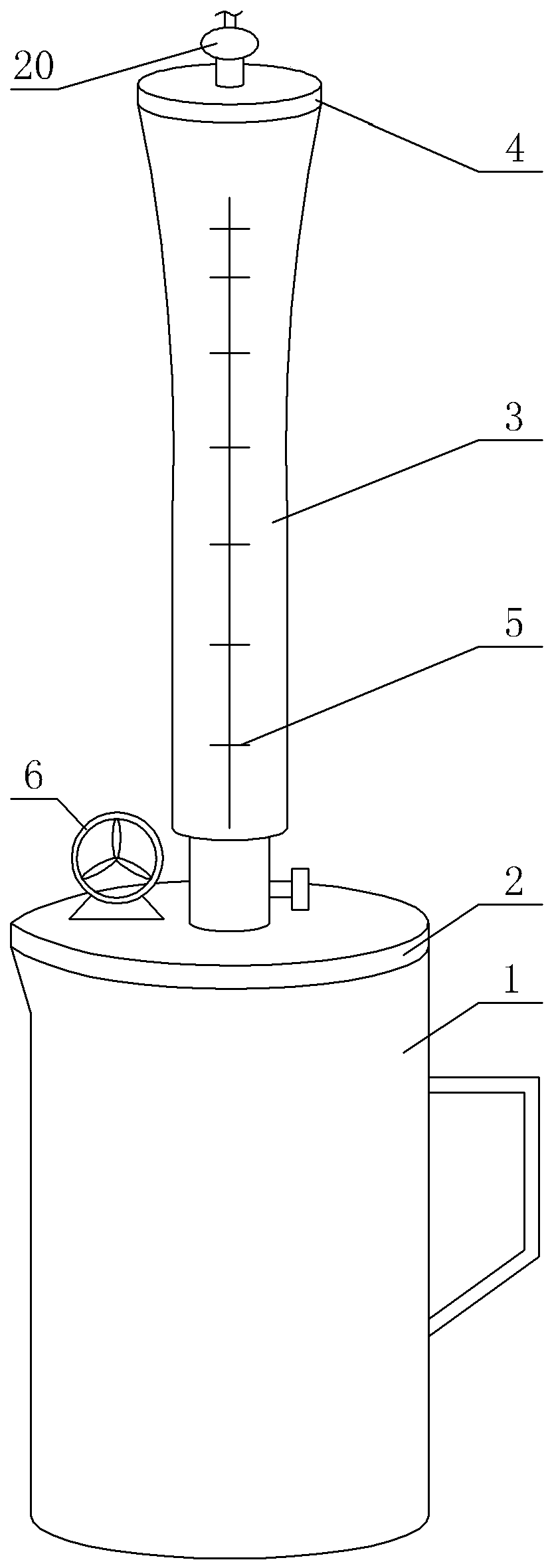
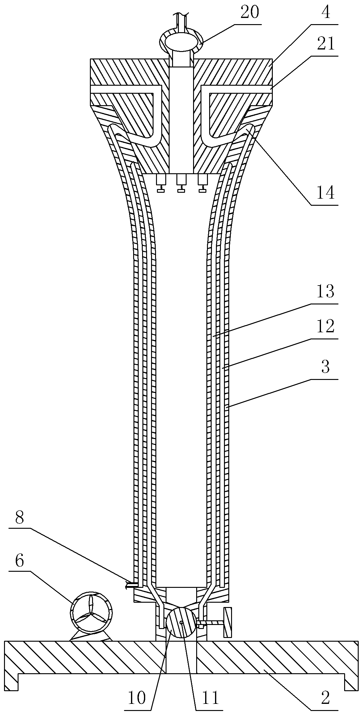
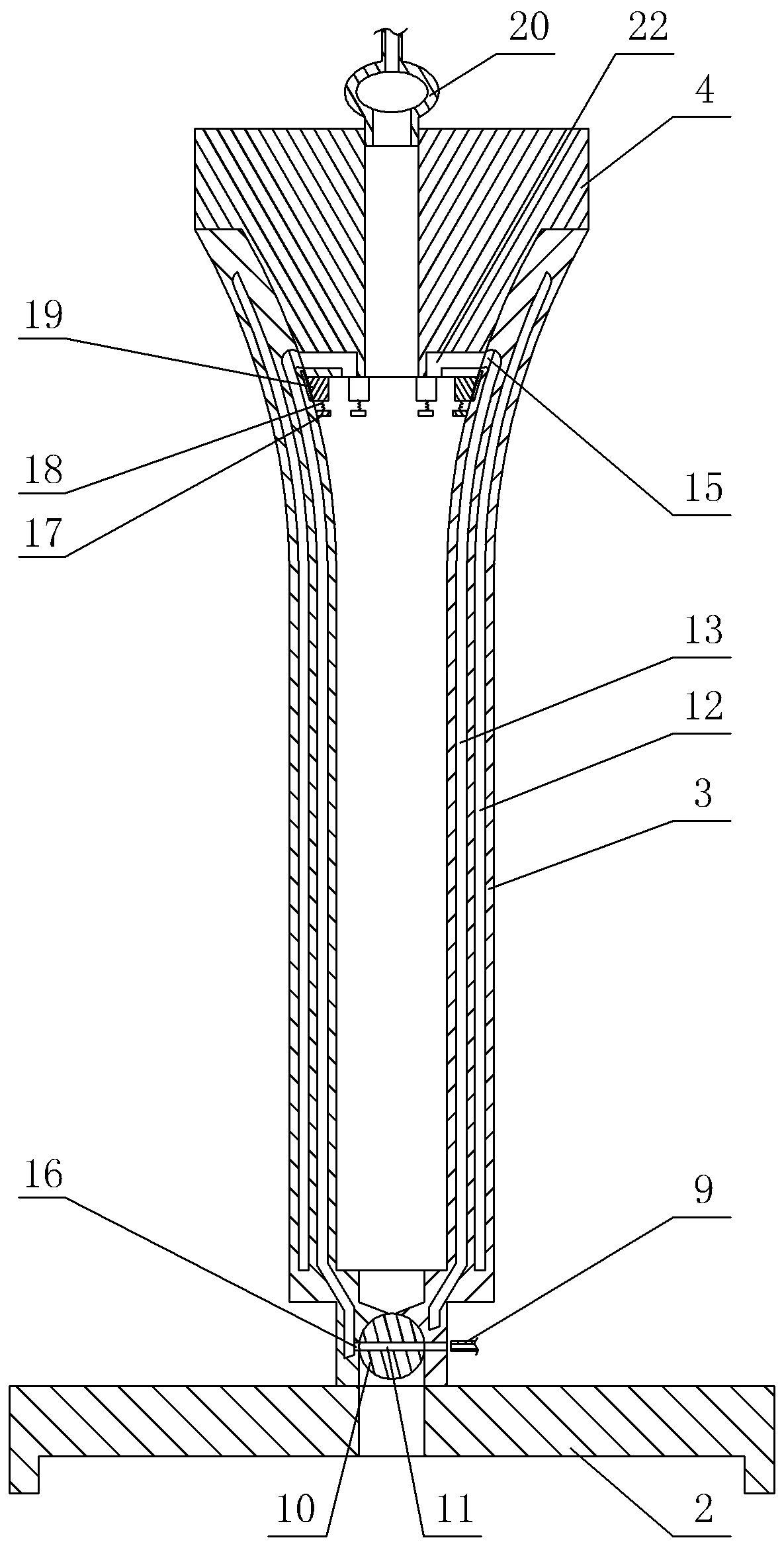
[0022] The reference signs in the accompanying drawings include: measuring cup body 1, cup cover 2, measuring cylinder 3, sealing plug 4, scale line 5, fan 6, cover 7, No. 1 hose 8, No. 2 hose 9, valve core 10. Leakage hole 11, outer cavity 12, inner cavity 13, air inlet hole 14, air outlet hole 15, negative pressure channel 16, support plate 17, spring 18, blocking plate 19, drainage ball 20, air outlet channel 21, Air intake channel 22.

[0023] The embodiment is basically as attached Figure 1-5 Shown: as figure 1 The precision drainage liquid measuring cup shown includes a measuring cup body 1, a cup cover 2, a measuring cylinder 3 and a sealing plug 4 from bottom to top. The central position is integrally cast, and the outer cylinder wall of the measuring cylinder 3 is engraved with a blue scale line 5, the scale line 5 at the bottom represents 5ml, and the difference between...


PUM


Abstract

The invention relates to the field of drainage liquid measuring cups, in particular to an accurate drainage liquid measuring cup. The measuring cup comprises a measuring cup body, a cup cover, a measuring cylinder, and a blocking plug. A valve is arranged on the lower end of the measuring cylinder. Scale lines are arranged on the outer cylinder wall of the measuring cylinder. An outer cavity and an inner cavity are arranged in the cylinder wall of the measuring cylinder. An air inlet hole communicates with the outer cavity and an air outlet hole communicates with the inner cavity are arrangedon the inner cylinder wall of the measuring cylinder. An air outlet channel is arranged on the blocking plug and can communicate with the air inlet hole. A fan is installed on the cup cover. Covers are installed at both the air inlet end and the air outlet end of the fan. The cover of the air outlet end of the fan communicates with the outer cavity, and the cover of the air inlet end of the fan can communicate with the inner cavity. By adopting the technical scheme, the workload of measuring the drainage liquid quantity of the nurse can be reduced; the drainage liquid in the measuring cylinderis directly drained into the measuring cup after use, and the measuring cup does not directly contact a drainage ball, thereby reducing the cross infection among different patients; meanwhile, the drainage liquid can be accurately measured, and not only a large amount but also a small amount of drainage liquid can be measured.

Description

technical field [0001] The invention relates to the field of drainage liquid measuring cups, in particular to a precise drainage liquid measuring cup. Background technique [0002] The precise measurement of drainage fluid plays a pivotal role in clinical nursing observation and provides an indispensable basis for doctors' diagnosis and treatment. In the process of patient drainage treatment, the nurse needs to measure the volume of the patient's drainage fluid. Usually, the drainage needle connected to the drainage ball through the drainage tube needs to be inserted into the patient's body, that is, inserted into the source of the drainage fluid, so that the drainage fluid passes through the patient's body. The drainage tube enters the drainage ball, and then the switch of the leakage tube under the drainage ball is turned on, and the drainage fluid is poured into the drainage cup. [0003] At present, the structure of the traditional drainage cup is relatively simple. Alt...

Claims


Application Information

Patent Timeline
Patent Type & Authority Patents(China)
IPC IPC(8): G01F19/00
CPCG01F19/00
Inventor 吴小月周迎春郭利均周蓉卢潇潇龚增义薛敏
Owner CHONGQING CANCER INST
Learn More