Data access device fixing structure
A technology of data accessor and fixed structure, which is applied in the direction of electrical digital data processing, digital data processing parts, instruments, etc., can solve the problem of inconvenient removal of hard disks, etc., and achieves the effect of tool-free disassembly and easy disassembly and assembly
- Summary
- Abstract
- Description
- Claims
- Application Information
AI Technical Summary
Problems solved by technology
Method used
Image

Examples
Embodiment Construction
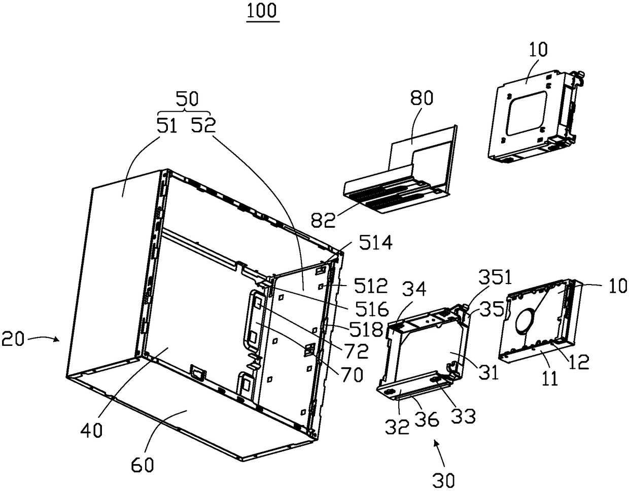
[0023] see Figure 1 to Figure 3 , in a preferred embodiment of the present invention, a data access device fixing structure 100 is used to fix at least one data access device 10 . The data access device fixing structure 100 includes a housing 20 and a fixing part 30 .
[0024] The data access device 10 includes two sidewalls 11 , each sidewall 11 is provided with two fixing holes 12 .
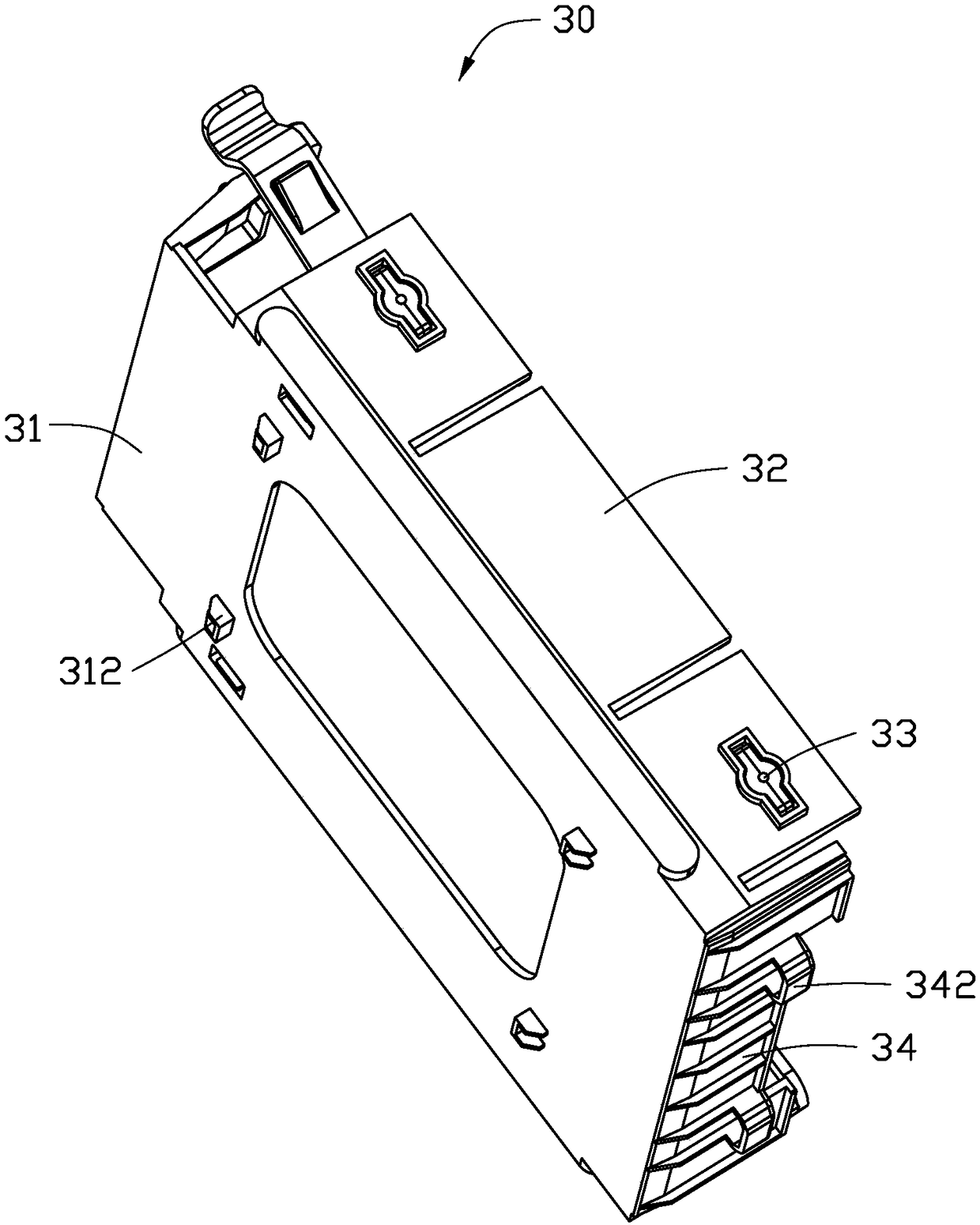
[0025] The fixing member 30 includes a fixing plate 31 , two clamping plates 32 vertically connected to two sides of the fixing plate 31 , and a stop plate 34 vertically connected to one end of the fixing plate 31 . Fasteners 33 are detachably installed at both ends of the clamping plate 32 , and the fasteners 33 can be inserted into the fixing holes 12 on the side wall 11 of the data access device 10 . Each clamping plate 32 is provided with a guide rail 36 . Two extensions 35 extend upward from the other end of the fixing plate 31 , and each extension 35 is respectively provided with a lo...
PUM
 Abstract
Description
Claims
Application Information
 - R&D
- Intellectual Property
- Life Sciences
- Materials
- Tech Scout
- Unparalleled Data Quality
- Higher Quality Content
- 60% Fewer Hallucinations
Browse by: Latest US Patents, China's latest patents, Technical Efficacy Thesaurus, Application Domain, Technology Topic, Popular Technical Reports.
© 2025 PatSnap. All rights reserved.Legal|Privacy policy|Modern Slavery Act Transparency Statement|Sitemap|About US| Contact US: help@patsnap.com