
An end insulation assembly of a direct-wound motor stator

A technology of end insulation and motor stator, which is applied to the shape/style/structure of electric components, windings, and winding insulation. It can solve problems such as inclined deformation of the inner wall, damage to the rotor, and enameled wires, so as to improve reliability and facilitate winding. Line work, unique design effects

Pending Publication Date: 2019-01-15
浙江迪贝电气股份有限公司
View PDF0 Cites 2 Cited by
  • Summary
  • Abstract
  • Description
  • Claims
  • Application Information

AI Technical Summary

Problems solved by technology

[0003] The prior art winding skeleton includes a plurality of inner wall parts. Since the stator winding has extruded inner wall parts (the higher the slot fullness rate, the more extruded), it is easy to cause the inner wall parts to be inclined and deformed toward the inner hole of the stator. Once the inner wall parts are deformed, the stator The winding collapses toward the inner hole of the stator. After the stator winding collapses, some wires in the loose stator winding easily enter the inner hole of the stator from the slot between adjacent inner walls, causing the rotor to rub and damage the enameled wire.

Method used


Image

  • An end insulation assembly of a direct-wound motor stator
  • An end insulation assembly of a direct-wound motor stator
  • An end insulation assembly of a direct-wound motor stator

Examples


Embodiment Construction

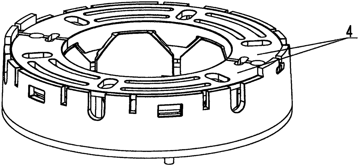
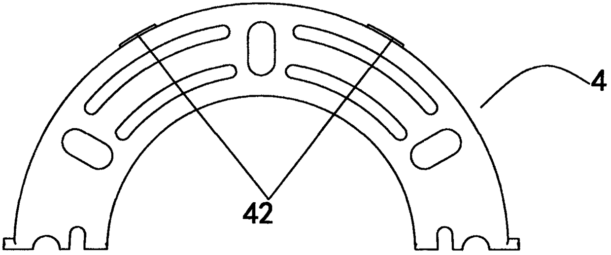
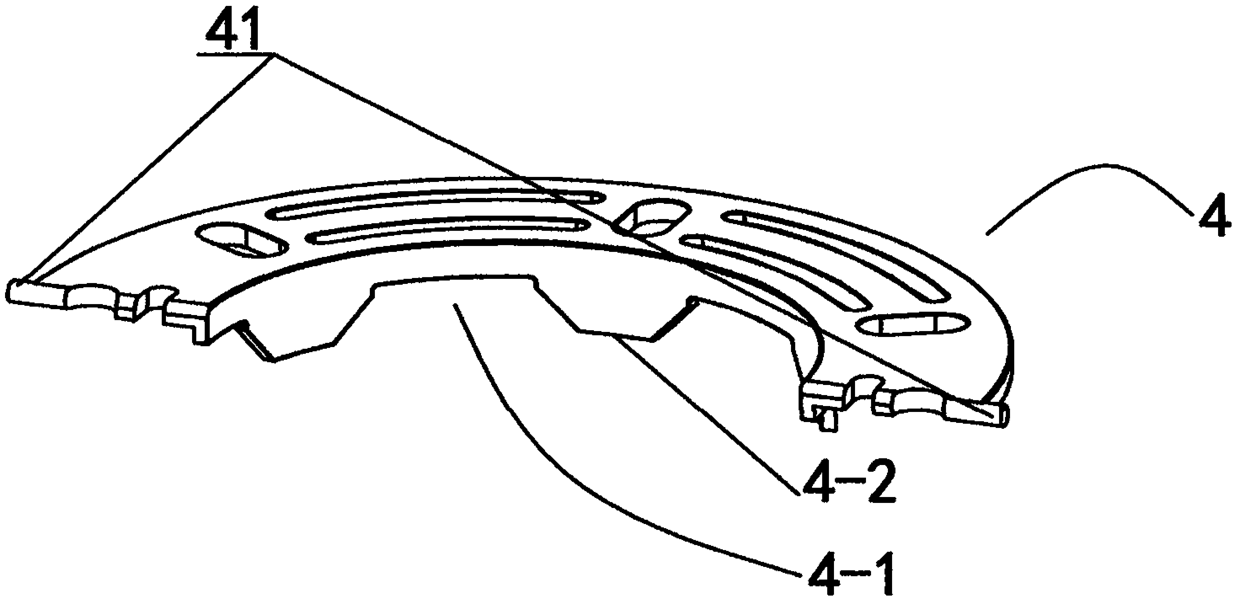
[0021] See Figure 1-7 As shown, an end insulation assembly of a straight-wound motor stator is protected by a coil insulation bracket K installed symmetrically up and down on both ends of the stator core G and a coil installed on at least one of the coil insulation brackets Composed of end caps, the coil protection end cap is composed of two semi-rings with symmetrical structures and 4 pairs. Wherein, each coil insulation support K includes an outer wall part 1 in the shape of a ring, an inner wall part 2 arranged at intervals in the circumferential direction, and a stator extending in the radial direction and connected with the inner wall part 2 and the outer wall part 1 for supporting the stator. A plurality of winding support parts 3 of the winding (known parts are not shown in the figure), there is a notch 20 between two adjacent inner wall parts 2, and the head ends 2-1 of the inner wall parts 2 are tongue-shaped, and adjacent Protrusions 21 and guiding slots 22 for ins...


PUM


Abstract

The invention discloses an end insulation assembly of a direct-wound motor stator, belonging to the motor stator technical field. Which is composed of two coil insulating brackets and coil protectionend caps installed to at least one coil insulating bracket, The end cover is composed of two half ring sheets. Each coil insulating bracket comprises an outer wall part, a plurality of inner wall parts and a plurality of winding supporting parts. There are notches between adjacent inner wall parts, and the head ends of the inner wall parts are tongue tips. The outer facades of adjacent inner wallparts near the notches are respectively provided with protrusions and guide slots formed between the protrusions. A plurality of stoppers and a notch located between adjacent stoppers are formed on the inner edges of the two half-ring segments. The outer wall part is symmetrically provided with a mounting groove and a buckle hole between the mounting grooves, and the outer edge of each half ring piece is provided with a clamp pin and a latch pin; The stopper extends between the head ends of adjacent inner wall portions, and the notch accommodates the head ends of the inner wall portions. The assembly of the invention is not only convenient to disassemble and deform, but also prevents the stator winding from collapsing and the wire at the end of the stator winding from being exposed to theoutside of the assembly.

Description

technical field [0001] The invention relates to an end insulation assembly of a direct-wound motor stator, belonging to the technical field of motor stator accessories. Background technique [0002] The winding frame is used for the insulation between the stator core and the stator winding (coil winding). The stator winding is wound on the winding frame by direct winding and embedded in the stator slot. The skeleton needs to reserve corresponding movement space for routing around the needle. The existing stator windings are usually relatively loose, which makes the stator windings easy to collapse toward the inner hole of the stator, and the end wires of the stator windings are easily exposed outside the winding skeleton, so that the wires (enameled wires) of the stator windings are easily damaged by foreign objects. The stator winding usually needs to be shaped, and the stator winding is bound and fixed with tape or rope. [0003] The prior art winding skeleton includes a...

Claims


Application Information

Patent Timeline
Patent Type & Authority Applications(China)
IPC IPC(8): H02K3/38H02K3/50
CPCH02K3/38H02K3/50
Inventor 赖家顺邢懿烨吴储正马树江
Owner 浙江迪贝电气股份有限公司
Learn More