Automatic stroke adjustment mechanism in brake apparatus
A technology of stroke adjustment and braking device, which is applied to slack adjusters, transportation and packaging, elevators in buildings, etc., and can solve problems such as increased noise, increased lining stroke, and increased elongation
- Summary
- Abstract
- Description
- Claims
- Application Information
AI Technical Summary
Problems solved by technology
Method used
Image
Examples
Embodiment approach 1
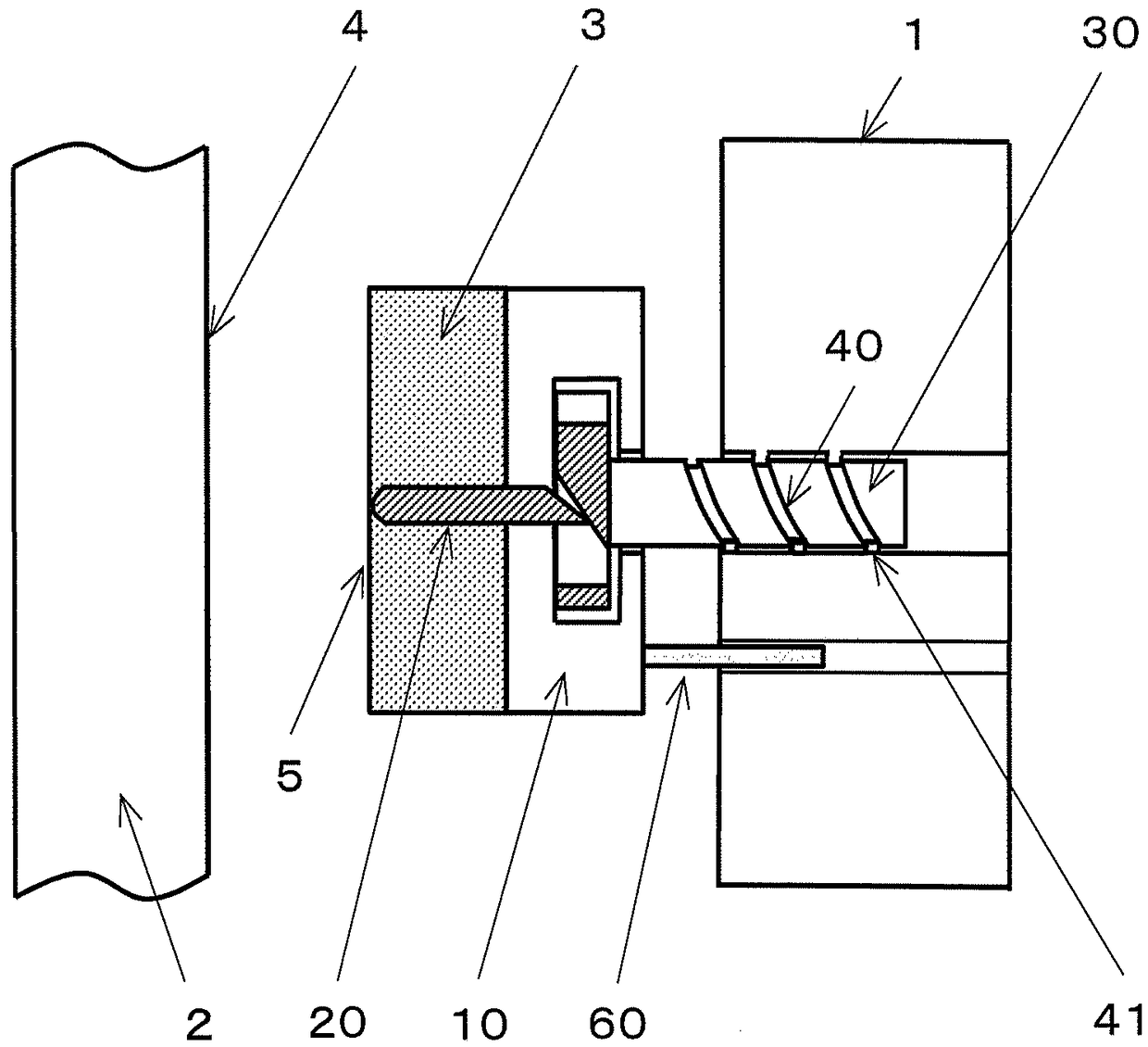
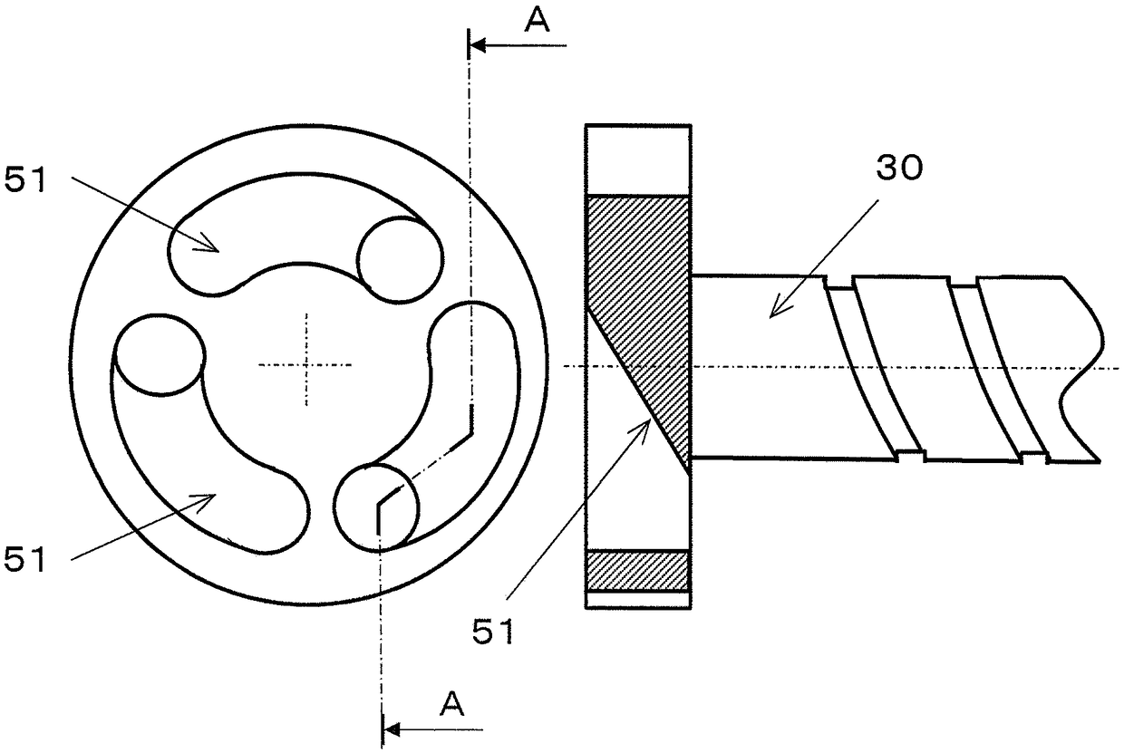
[0024] use Figure 1 to Figure 5 An automatic stroke adjustment mechanism according to an embodiment of the present invention will be described. figure 1 is a diagram showing the overall structure of the brake, figure 2 is a diagram showing the displacement member 20, image 3 is a diagram showing the stroke adjustment member 30 . and, Figure 4 shown in figure 1 The state of the lining 3 in the brake before wear, Figure 5 The state of the lining 3 after wear is shown.
[0025] exist figure 1 In this case, the lining 3 is held by the holding member 10 and connected to the stroke adjustment member 30 . The stroke adjustment member 30 has a first external thread portion 40 , and the first external thread portion 40 is screwed to the first internal thread portion 41 of the armature 1 . The friction surface 5 of the lining 3 and the braking surface of the brake disc 2 can be adjusted by rotating the first external thread portion 40 of the stroke adjustment member 30 in t...
Embodiment approach 2
[0035] Figure 9 It is the automatic stroke adjustment mechanism of Embodiment 2 of this invention. The automatic stroke adjustment mechanism of the second embodiment includes a displacement member 23 , a first bevel gear 80 , a second bevel gear 81 meshing with the first bevel gear 80 , and a stroke adjustment member 32 .
[0036] An engaging portion 82 that engages with an engaged portion 83 of the first bevel gear 80 is provided at the front end of the displacement member 23 , and the second bevel gear 81 is fixed to the stroke adjustment member 32 . Furthermore, the stroke adjustment member 32 is provided with a second external thread portion 44 which is screwed into the second internal thread portion 45 provided on the holding member 12 .
[0037] When the lining 3 is worn, the displacement member 23 is displaced, and the engaging portion 82 provided at the tip of the displacement member 23 rotates the first bevel gear 80 through the engaged portion 83 provided on the fi...
Embodiment approach 3
[0040] Figure 10 It is the automatic stroke adjustment mechanism of Embodiment 3 of this invention. Such as Figure 10 As shown, the automatic stroke adjustment mechanism of Embodiment 3 has a displacement member 24 , a stroke adjustment member 33 and a gear 90 .
[0041] The gear 90 can only rotate in one direction, so that the stroke adjustment member 33 can only move in the direction of the brake disc 2 . The displacement member 24 has a first comb 91 that meshes with a gear 90 , and the stroke adjustment member 33 has a second comb 92 that meshes with a gear 90 . Furthermore, the first comb blade 91 and the second comb blade 92 are engaged with the gear 90 so as to face each other.
[0042]When the brake works and the friction surface 5 of the lining 3 is pressed by the braking surface 4 of the brake disc 2, the stroke adjustment member 33 has a force to move the stroke adjustment member 33 to the armature 1 side, but since the gear 90 does not rotate , and thus will ...
PUM
 Abstract
Description
Claims
Application Information
 - R&D
- Intellectual Property
- Life Sciences
- Materials
- Tech Scout
- Unparalleled Data Quality
- Higher Quality Content
- 60% Fewer Hallucinations
Browse by: Latest US Patents, China's latest patents, Technical Efficacy Thesaurus, Application Domain, Technology Topic, Popular Technical Reports.
© 2025 PatSnap. All rights reserved.Legal|Privacy policy|Modern Slavery Act Transparency Statement|Sitemap|About US| Contact US: help@patsnap.com


