
Novel vertical energy-saving oil pumping unit

A pumping unit and vertical technology, applied in the field of new vertical energy-saving pumping units, can solve the problems of poor energy-saving effect of vertical pumping units, etc.

Inactive Publication Date: 2013-11-06
HEILONGJIANG WANYIDA GASOLINEEUM ENG
View PDF3 Cites 0 Cited by
  • Summary
  • Abstract
  • Description
  • Claims
  • Application Information

AI Technical Summary

Problems solved by technology

[0004] The purpose of the present invention is to provide a new type of vertical energy-saving pumping unit, which is used to solve the problem of poor energy-saving effect of the existing vertical type of oil pumping unit

Method used


Image

  • Novel vertical energy-saving oil pumping unit
  • Novel vertical energy-saving oil pumping unit
  • Novel vertical energy-saving oil pumping unit

Examples


Embodiment 1

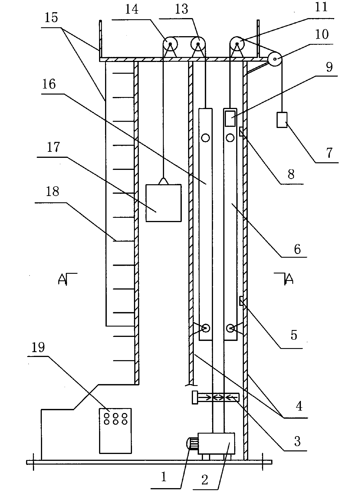
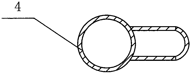
[0020] figure 1 , figure 2 A structural schematic diagram of the first embodiment of the present invention is provided, as shown in the figure, the bracket 4 of this new vertical energy-saving pumping unit is a combination of a cylindrical metal hollow cylinder and a flat metal hollow cylinder , the upper end of the bracket 4 is a platform, the balance weight 17 can move up and down in the cylindrical metal hollow cylinder, two gravity distributors (6, 16) are installed in the flat metal hollow cylinder, the motor 1 and the motor Drag device 2 is installed on the base of support 4, and electric control box 19 is also installed on the base of support 4, guardrail 15 and climbing ladder 18 are installed on support 4, for the convenience of maintenance, also be provided with manhole on support; Balance counterweight 17 It is connected to the gravity distributor 16 through the lifting system; the sucker rod system is connected to another gravity distributor 6 through the self-ba...

Embodiment 2

[0027] Compared with Embodiment 1, this embodiment differs in that the two gravity distributors (6, 16) are respectively connected to the motor drive device 2 through respective flat flexible belts, because the flat flexible belts will be laminated one by one. Layers are evenly wound on the cylinder 36 of the motor drive device, so the power centralizing device 3 is also omitted in the present embodiment, specifically as Figure 7 Shown, others are identical with embodiment 1.

Embodiment 3

[0029] Compared with Embodiment 1, the difference of this embodiment is that the balance counterweight anti-falling system is added. The steel wire rope will break due to fatigue due to long-time work. Once the steel wire rope breaks, the balance weight 17 will fall down, causing danger. In order to prevent this phenomenon from happening, a balance counterweight anti-falling system is added. The balance counterweight anti-falling system is composed of an anti-off steel wire rope and a rotating wheel. The rotating wheel is installed on the base of the bracket 4. There is a gravity spring on the rotating wheel. One end of the anti-off steel wire rope is fixed on the gravity distributor 16 connected to the lifting system. On the movable pulley block, the other end goes around the rotating wheel of the base downwards, and then upwards is connected to the movable pulley block of the gravity distributor 6 connected with the self-balancing system of the rope hanger. 6,16) two moving ...


PUM


Abstract

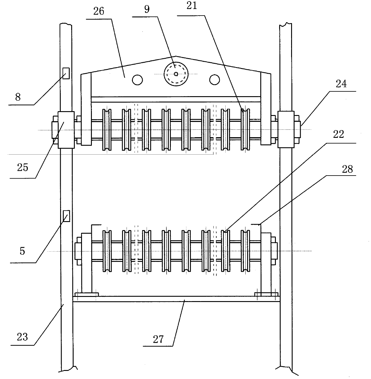
The invention relates to a novel vertical energy-saving oil pumping unit which comprises a motor on a base, a motor dragging device, weight distributors, a polished rod eye self-balance system, a balance weight and a sucker rod system, wherein the balance weight is connected with one weight distributor through a lifting system, the sucker rod system is connected with the other weight distributor through the polished rod eye self-balance system, and the two weight distributors are connected with the motor dragging device through respective flat flexible bands; each weight distributor is formed by arranging an upper pulley block and a lower pulley block on a support frame, the upper pulley block is a movable pulley block and can slide up and down along the support frame, the lower pulley block is a fixed pulley block and fixed on the support frame, and the flat flexible bands sequentially penetrate through the upper pulley block and the lower pulley block; and the motor dragging device is a reversible roller. After the difference of the weight of the sucker rod system and the weight of the balance weight is decomposed by adopting the weight distributors, the motor provides power corresponding to the difference value, therefore, the power of the motor provided by the motor dragging device is small, and the effects for saving power and saving energy are realized.

Description

[0001] This application is a divisional application of the invention patent application "vertical energy-saving pumping unit". The invention name of the original application is: vertical energy-saving pumping unit, the application date is June 19, 2008, and the application number is: 200810110975.4. 1. Technical field: [0002] The invention relates to an oil pumping unit used in oil exploitation, in particular to a novel vertical energy-saving oil pumping unit. 2. Background technology: [0003] In the process of oil extraction, it is necessary to use pumping units to pump crude oil up from the ground. With the continuous advancement of technology, the vertical pumping unit omits the crank linkage mechanism, beams, beams, and donkeys of the traditional beam pumping unit. The first-class mechanism reduces mechanical loss and achieves energy-saving effects to varying degrees, and is gradually being applied. For example, a Chinese utility model patent whose patent number is ZL...

Claims


Application Information

Patent Timeline
Patent Type & Authority Patents(China)
IPC IPC(8): E21B43/00
Inventor 刘星海祝丽华
Owner HEILONGJIANG WANYIDA GASOLINEEUM ENG
Learn More