Head-up display device and cold mirror

A head-up display and display light technology, applied in the field of cold light mirror, can solve the problem of display quality degradation

Active Publication Date: 2019-01-15
DENSO CORP
View PDF6 Cites 3 Cited by
  • Summary
  • Abstract
  • Description
  • Claims
  • Application Information

AI Technical Summary

Problems solved by technology

[0006] However, in the case of adopting the cold mirror unit of Patent Document 1, there is a concern that the display quality of virtual images may be lowered due to lowering of brightness and deterioration of chromaticity.

Method used


Image

  • Head-up display device and cold mirror
  • Head-up display device and cold mirror
  • Head-up display device and cold mirror

Examples


no. 1 approach

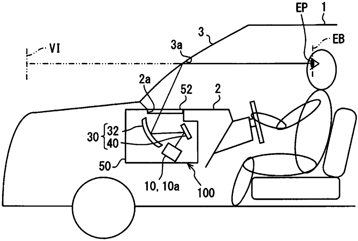
[0039] Such as figure 1 As shown, the HUD device 100 based on the first embodiment of the present disclosure is mounted on a vehicle 1 which is a type of mobile body, and is housed in an instrument panel 2. The HUD device 100 projects display light onto the windshield 3 as a projection member of the vehicle 1 through a projection window 2 a provided on the upper surface of the instrument panel 2. The display light is reflected by the windshield 3, and thus the HUD device 100 displays the image as a virtual image in a manner that the passengers of the vehicle 1 can visually recognize. That is, the display light reflected by the windshield 3 reaches the visual confirmation area EB set in the interior of the vehicle 1, and a passenger whose eyepoint EP is located in the visual confirmation area EB perceives the display light as a virtual image VI. Moreover, passengers can recognize various information through the virtual image VI. As various information displayed as an image by t...

no. 2 approach

[0091] Such as Figure 14-16 As shown, the second embodiment of the present disclosure is a modification of the first embodiment. The description of the second embodiment will focus on the differences from the first embodiment.

[0092] Such as Figure 14 As shown, the cold light mirror portion 240 of the second embodiment has a second wavelength region blocking mirror 242 and an infrared region blocking mirror 246.

[0093] The second wavelength region blocking mirror 242 is arranged on the optical path OP of the display light on the side of the display light projection unit 10 rather than the infrared region blocking mirror 246. The second wavelength region blocking mirror 242 has a mirror substrate 243 and an optical multilayer film 244. The mirror substrate 243 is formed of, for example, synthetic resin, glass, or the like in a flat plate shape having translucency.

[0094] The optical multilayer film 244 is formed on a surface 242 a of the mirror substrate 243 facing the disp...


PUM


Abstract

A display light projection unit (10) projects an image as a display light including a plurality of wavelengths in the visible region. A light guide unit (30) includes a cold mirror unit (40, 240) thatguides the display light from the display light projection unit (10) toward a projection window side. The light guide unit (30) reflects the display light by using an optical multi-layer film (44, 244, 248). In an XYZ color system, a wavelength region between a wavelength ([Lambda]zm) at which the value of a color-matching function Z becomes the greatest and a wavelength ([Lambda]ym) at which thevalue of a color-matching function Y becomes the greatest is a first wavelength region (WR1). A wavelength region between the wavelength ([Lambda]ym) at which the value of the color-matching functionY becomes the greatest and a wavelength ([Lambda]xm) at which a color-matching function X becomes the greatest is a second wavelength region (WR2). A reflectance, with respect to the display light, of the cold mirror unit (40, 240) and having the smallest value among reflectances at respective wavelengths within the target wavelength region is the minimum reflectance. The minimum reflectance in the second wavelength region is greater than the minimum reflectance in the first wavelength region.

Description

[0001] Cross references to related applications [0002] This application is based on the Japanese application number 2016-112822 for which it applied on June 6, 2016, and the content of description is quoted here. Technical field [0003] The present disclosure relates to a head-up display device (hereinafter referred to as a HUD device for short) and a cold light mirror suitable for the HUD device. Background technique [0004] Conventionally, there has been known a HUD device that is mounted on a mobile body and displays a virtual image that can be visually recognized by passengers by projecting display light on a projection member through a projection window. The HUD device disclosed in Patent Document 1 includes: a display light projection unit that projects an image with display light of multiple wavelengths including a visible area; and a light guide unit that guides the display light from the display light projection unit to the projection window . Furthermore, the light g...

Claims


Application Information

Patent Timeline
Patent Type & Authority Applications(China)
IPC IPC(8): G02B27/01B60K35/00G02B5/28
CPCB60K35/00G02B5/28G02B27/01G02B27/0101G02B2027/0112G02B2027/0118B60K2370/334B60K2370/23G02B2027/0114B60K2370/1529G02B5/26G02B5/208B60K2370/31B60K2370/336G02B5/282
Inventor 横江润也南原孝启
Owner DENSO CORP
Why Eureka
Try Eureka