
Pulse wave sensor, sensor array, and pulse wave measuring device adopting the same

A sensor array and sensor technology, applied in the field of radial artery pulse wave collection devices, pulse wave sensors, and pulse wave measurement devices, can solve the problems of mutual interference between sensors, failure to output pulse waves, and influence on the accuracy of pulse waves, etc., to maintain Sensitivity, high sensitivity, good fit effect

Active Publication Date: 2019-01-18
INST OF MICROELECTRONICS CHINESE ACAD OF SCI
View PDF6 Cites 8 Cited by
  • Summary
  • Abstract
  • Description
  • Claims
  • Application Information

AI Technical Summary

Problems solved by technology

This leads to the fact that the range of the small-range pressure sensor cannot meet the test requirements, and the output voltage of the large-range sensor has a low resolution ability for force, and cannot output morphologically meaningful pulse waves under low pressure.
[0004] In addition, there are two problems in the existing sensor array. One problem is that the sensor array cannot meet the problem of fitting the arms of different groups of people. The poor fit of the array cannot guarantee the fidelity of the pulse wave collection; The problem of mutual interference between sensors can cause pulse waves collected by adjacent sensors to overlap each other, affecting the accuracy of pulse waves

Method used


Image

  • Pulse wave sensor, sensor array, and pulse wave measuring device adopting the same
  • Pulse wave sensor, sensor array, and pulse wave measuring device adopting the same
  • Pulse wave sensor, sensor array, and pulse wave measuring device adopting the same

Examples


Embodiment Construction

[0034] In order to make the object, technical solution and advantages of the present invention clearer, the present invention will be further described in detail below in conjunction with specific embodiments and with reference to the accompanying drawings.

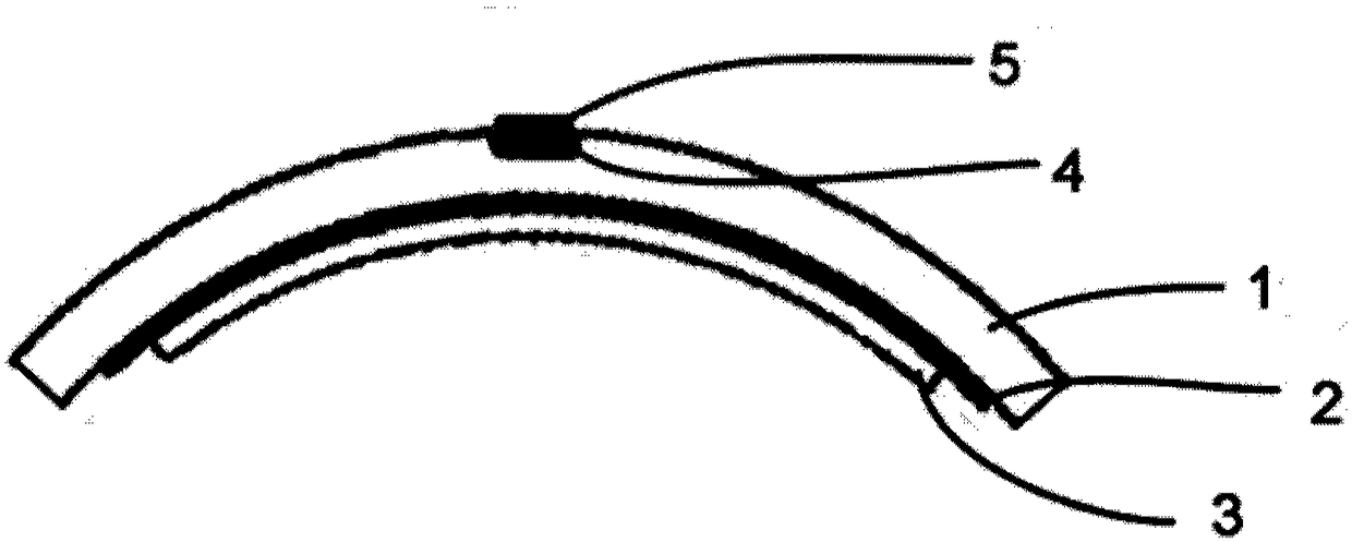
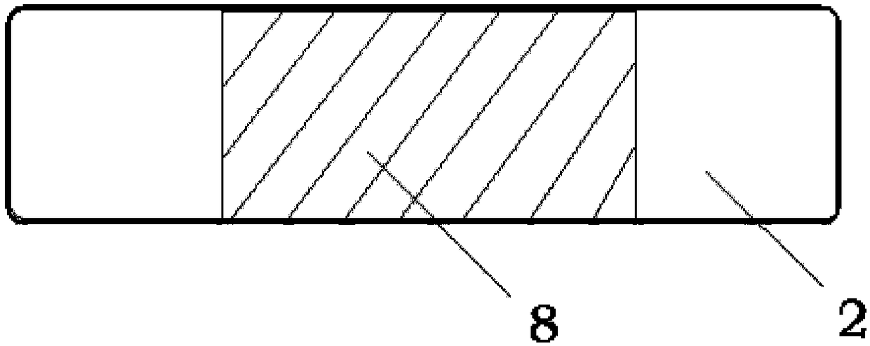
[0035] The invention aims to solve the problem that the pulse wave acquisition device in the prior art cannot accurately and comprehensively reflect the pulse condition information of the human body. The range of traditional piezoresistive sensors is inversely proportional to the sensitivity. Pulse wave sensors need to capture weak pulse signals in a large range, while traditional piezoresistive sensors have low sensitivity in a large range. In order to solve this problem, in the present invention, the static pressure signal and the dynamic pulse wave pressure signal are measured separately, the piezoelectric film is used to measure the dynamic pressure fluctuation, and the piezoresistive sensor is used to measure the stat...


PUM


Abstract

The invention relates to a pulse wave sensor, a sensor array and a pulse wave measuring device adopting the same. The pulse wave sensor comprises a sensor skeleton, a flexible piezoelectric sensor anda static pressure sensor, wherein the flexible piezoelectric sensor is used for sensing pulse waves; The static pressure sensor is used for measuring the static pressure exerted on the pulse wave sensor. The sensor skeleton is used for fixing the flexible piezoelectric sensor and the static pressure sensor. The sensor of the invention measures the static pressure signal and the dynamic pulse wavepressure signal separately, the piezoelectric film is used to measure the dynamic pressure fluctuation, and the piezoresistive sensor measures the static pressure, so that the dynamic sensitivity isnot affected by the static pressure measuring range, and the high sensitivity to the pulse wave can be maintained under the wide range of static pressure; The sensor of the invention adopts a flexibleskeleton, so that the array composed of the sensor can meet the characteristics of the wrists of different crowds and realize good bonding to the surface of the arm.

Description

technical field [0001] The invention belongs to the technical field of noninvasive detection of human health status, and in particular relates to a device for collecting radial artery pulse waves, and more specifically relates to a pulse wave sensor, a sensor array and a pulse wave measuring device using the same. Background technique [0002] Pulse waveform can reflect the degree of human health and various diseases. Pulse wave measurement methods are divided into invasive and non-invasive. Invasive pulse wave measurement methods cause great harm to patients, while non-invasive methods do little harm to patients, such as pressure sensors, ultrasonic sensors, photoelectric sensors, etc. These sensors all enable non-invasive measurement of pulse waves. However, the current mainstream method of measuring pulse wave is still the pressure sensor to measure the pulse wave. Some devices use thin-film piezoresistive pressure sensors to collect pulses at multiple points on the wr...

Claims


Application Information

Patent Timeline
Patent Type & Authority Applications(China)
IPC IPC(8): A61B5/02
CPCA61B5/02A61B5/6824A61B2562/0247
Inventor 张劭龙刘苏张以涛耿兴光张俊侯洁娜张海英
Owner INST OF MICROELECTRONICS CHINESE ACAD OF SCI
Learn More