Magnetoelectric rotation speed generator

A magnetoelectric sensor and generator technology, which is applied in the direction of instruments, electromechanical devices, electrical components, etc., can solve the problems of inability to simulate the engine speed signal, amplitude increase, etc., and achieve the speed signal source is true and reliable, the structure is simple, and the scope of application wide effect

Inactive Publication Date: 2019-12-31
HARBIN ENG UNIV
View PDF7 Cites 1 Cited by
  • Summary
  • Abstract
  • Description
  • Claims
  • Application Information

AI Technical Summary

Problems solved by technology

The disadvantage is that it cannot simulate the speed signal generated during the actual operation of the engine, its amplitude increases with the increase of the speed, and it is accompanied by obvious clutter (such as figure 2 )

Method used


Image

  • Magnetoelectric rotation speed generator
  • Magnetoelectric rotation speed generator
  • Magnetoelectric rotation speed generator

Examples


Embodiment Construction

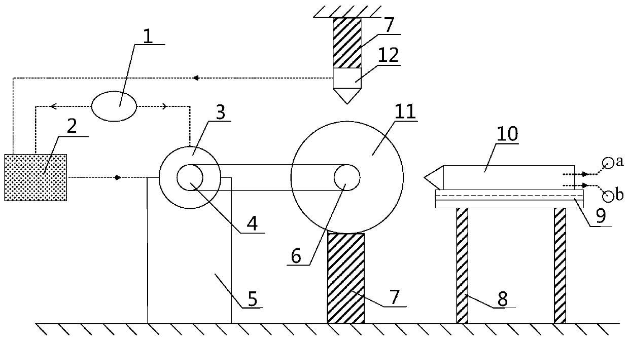
[0018] The present invention is described in more detail below in conjunction with accompanying drawing example:

[0019] combine Figure 1-3 , the magnetoelectric speed generator of the present invention includes a brushless DC motor 3, a magnetic gear 11, a magnetoelectric sensor 10, a Hall sensor 12, a rotary axial displacement device 9, a PID controller 2, a battery pack 1, a chain Wheel Ⅰ4, sprocket Ⅱ6, fixed bracket, etc. The battery pack 1 transmits electric energy to the PID controller 2 and the brushless DC motor 3 through the circuit, the PID controller 2 is connected with the brushless DC motor 3 through the circuit, and the power output end of the brushless DC motor 3 is coaxially connected with the sprocket I4, The magnetic gear 11 is coaxially connected with the sprocket Ⅱ6, and the sprocket Ⅰ4 and the sprocket Ⅱ6 are connected through a transmission chain. The number of teeth of the two sprockets is equal, and the transmission ratio is 1:1. The motor is install...


PUM


Abstract

The invention aims to provide a magnetoelectric rotation speed generator. The magnetoelectric rotation speed generator comprises a brushless direct-current motor, a battery pack, a PID controller anda magnetic gear; the battery pack is connected with the brushless direct-current motor and the PID controller; the power output end of the brushless direct-current motor is coaxially connected with afirst chain wheel; a magnetic gear is coaxially connected with a second chain wheel; the first chain wheel and the second chain wheel are connected through a transmission chain; the brushless direct-current motor is installed on a first fixing support; the center shaft of the magnetic gear is installed on a second fixing support; a Hall sensor is arranged right above the magnetic gear; the Hall sensor is installed on a fourth fixing support; and a magnetoelectric sensor is installed on a third fixing support and located beside the magnetic gear. According to the magnetoelectric rotation speedgenerator of the invention, a speed signal source received by the sensor is real and reliable, and the inaccuracy of rotation speed signal simulation is overcome; and the PID controller can realize the constant speed function of the motor through the signal feedback of the Hall sensor. The magnetoelectric rotation speed generator has the advantages of simple structure, convenient operation, wide application range, high detection speed and high precision.

Description

technical field [0001] The invention relates to a rotational speed detection system, in particular to a rotational speed detection system of an engine. Background technique [0002] With the structure and control strategy of the engine electronic control system becoming more and more complex, the difficulty of research and development of the electronic control system and the workload of experiments have greatly increased, and the cost has also increased significantly. The V-type development model has become the mainstream of the engine ECU (Electronic Control Unit, electronic control unit) development process. In the hardware-in-the-loop simulation, in order to cooperate with the development of ECU software, it is necessary to provide the engine speed signal to verify the correctness of the software algorithm. The commonly used method at this stage is to use the speed simulator to simulate and output the speed (frequency) signal and given current signal required by the site ...

Claims


Application Information

Patent Timeline
IPC IPC(8): G01M15/02G05B23/02H02K29/14
CPCG01M15/02G05B23/0205H02K29/14
Inventor 杨传雷李旸王银燕王贺春
Owner HARBIN ENG UNIV
Why Eureka
Try Eureka