[0029] In order to facilitate the understanding of the present invention, the present invention will be described more fully below with reference to the relevant drawings. The drawings show preferred embodiments of the present invention. However, the present invention can be implemented in many different forms and is not limited to the embodiments described herein. On the contrary, the purpose of providing these embodiments is to make the understanding of the disclosure of the present invention more thorough and comprehensive.
[0030] It should be noted that when an element is referred to as being "fixed to" another element, it can be directly on the other element or a central element may also exist. When an element is considered to be "connected" to another element, it can be directly connected to the other element or an intermediate element may be present at the same time. The terms "vertical", "horizontal", "left", "right" and similar expressions used herein are for illustrative purposes only.
[0031] Unless otherwise defined, all technical and scientific terms used herein have the same meaning as commonly understood by those skilled in the technical field of the present invention. The terminology used in the specification of the present invention herein is only for the purpose of describing specific embodiments, and is not intended to limit the present invention.
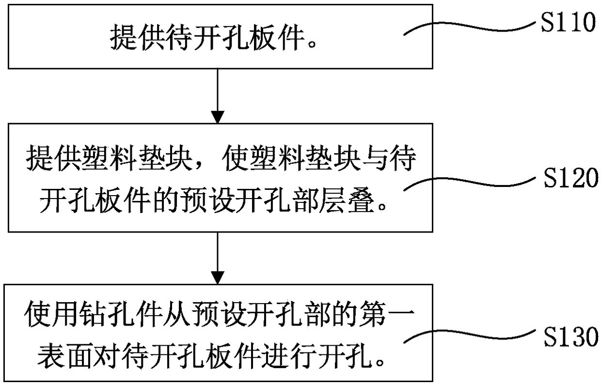
[0032] Such as figure 1 Said, a method for opening a plate in an embodiment includes the following steps:
[0033] Step S110: Provide the plate to be holed.
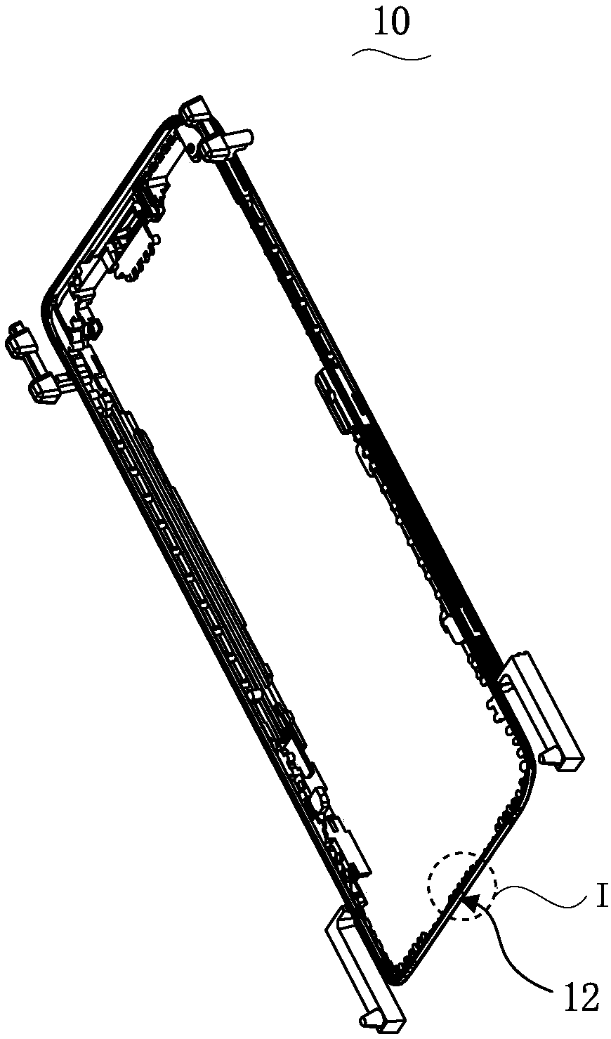
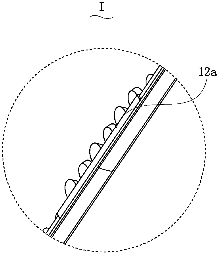
[0034] Such as Figure 2 ~ Figure 3 As shown, the plate 10 to be perforated has a predetermined opening portion 12, and the predetermined opening portion 12 has a first surface 12a and a second surface (not shown) opposite to the first surface.
[0035] Step S120: Provide a plastic cushion block, the plastic cushion block has a bonding surface, and the plastic cushion block is layered with the predetermined opening portion, so that the bonding surface closely fits the second surface of the plastic cushion block.
[0036] Such as Figure 4 As shown, the plastic block 20 has a bonding surface 20a.
[0037] Further, in one embodiment, the step of laminating the plastic spacer block and the predetermined opening portion so that the bonding surface closely adheres to the second surface of the plastic spacer block includes:
[0038] Step S122: Provide a fixing seat.
[0039] Such as Figure 5 As shown, the fixing seat 30 is provided with a receiving groove 32.
[0040] Step S124: Place the plastic cushion block in the receiving groove.
[0041] Such as Figure 6-7 As shown, the plastic block 20 is received in the receiving groove 32 on the fixing base 30.
[0042] Step S126: Mount the plate to be perforated on the fixing seat, and make the second surface of the predetermined perforated portion closely fit the bonding surface.
[0043] Such as Figure 6-8 As shown, in one embodiment, the plastic spacer block 20 is placed in the receiving groove 32 of the fixing seat 30, and the plane of the slot of the receiving groove 32 is flush with the bonding surface 20a of the plastic spacer block. The plate 10 to be perforated is mounted on the fixing base 30 with the fixing frame 40 and the fixing cover 50, and the second surface (not shown) of the predetermined opening portion 12 is connected to the bonding surface 20a of the plastic pad 20 Fits tightly.
[0044] Step S130: Use a drilling element to drill holes from the first surface of the predetermined opening portion to the plate to be perforated, so that the drilling element sequentially passes through the first surface, the second surface and the bonding surface of the plastic pad; In order to form a through hole in the predetermined opening portion.
[0045] In one of the embodiments, the material of the predetermined opening portion 12 is plastic.
[0046] In one of the embodiments, the difference between the surface roughness (Ra) of the second surface (not shown) of the predetermined opening portion 12 and the surface roughness (Ra) of the bonding surface 20a of the plastic pad 20 is 0.2 Below μm.
[0047] It can be understood that as long as the second surface (not shown) of the predetermined opening portion 12 can be closely attached to the bonding surface 20a of the plastic pad 20, the second surface (not shown) is the surface of the bonding surface 20a. The difference in roughness (Ra) is not limited to within 0.2 μm.
[0048] In one embodiment, the diameter of the through hole (not shown) formed in the opening portion 12 is preset to be 0.5 mm or less.
[0049] The above-mentioned hole-opening method is applied to panels with a smaller aperture, and is especially suitable for panels with a preset aperture below 0.4 mm.
[0050] In one embodiment, the material of the plastic block 20 is PBT or PC.
[0051] It can be understood that the plastic spacer 20 is used as an auxiliary material for the opening of the plate 10, which is a disposable consumable and is not limited to PBT or PC materials. As long as the surface roughness and hardness can meet certain requirements, the plastic pad 20 can also be made of PA46, PA66 and other materials.
[0052] In one of the embodiments, the drilling element (not shown) is a drill, and the feed rate of the drilling element (not shown) is 300 mm/min to 400 mm/min.
[0053] It can be understood that the use of this feed amount can ensure the quality of the hole and effectively protect the hole wall of the through hole (not shown). Especially when the feed rate of 400mm/min is selected, the hole quality is better.
[0054] In one embodiment, the above-mentioned method for opening the plate is used in the manufacture of the middle frame, back cover or bottom plate of a mobile electronic device.
[0055] It can be understood that the processed panels that use the above-mentioned hole-opening method to make holes are not limited to making the middle frame, back cover or bottom plate of a mobile electronic device. It can also be used in the production of other panels that require smaller apertures.
[0056] Use the hole-opening method of the present invention to open holes on 50 plates to be holed, use traditional hole-opening methods to open holes on another 10 plate pieces to be holed, and use a 2.5-dimensional projector to perform holes on each plate The burrs at the openings of the parts have been measured and counted. The statistical results are shown in the table below.
[0057] Table 1 Statistics of the burr length of the hole in the plate
[0058]
[0059] It can be seen from the above table that the average burr length of the opening part of the plate using the present invention is 0.0038mm, and some even have no burr; while the average burr length of the opening part of the plate using the traditional method is 0.08mm , The difference between the two is at least an order of magnitude.
[0060] In summary, the hole-opening method of the above-mentioned plate has at least the following advantages:
[0061] (1) The above-mentioned method for opening the plate is to pad the plastic spacer on one side of the second surface of the predetermined opening, so that the bonding surface of the plastic spacer is closely attached to the second surface of the predetermined opening. Synthesize "one piece", so that the burrs that will inevitably appear at the bottom edge of the through hole using the traditional hole-opening method are transferred to the plastic spacer block that is "one-piece" with the preset hole, so the plate burrs created by this method are very short , And some even have no burrs.
[0062] (2) Because the board burrs processed by this method meet the process requirements, there is no need to use dry ice to remove burrs later, which can simplify the hole-opening process of the board, improve production efficiency and product yield.
[0063] The technical features of the above-mentioned embodiments can be combined arbitrarily. In order to make the description concise, all possible combinations of the various technical features in the above-mentioned embodiments are not described. However, as long as there is no contradiction in the combination of these technical features, All should be considered as the scope of this specification.
[0064] The above-mentioned embodiments only express several implementation modes of the present invention, and the description is relatively specific and detailed, but it should not be understood as a limitation on the scope of the invention patent. It should be pointed out that for those of ordinary skill in the art, without departing from the concept of the present invention, several modifications and improvements can be made, and these all fall within the protection scope of the present invention. Therefore, the protection scope of the patent of the present invention should be subject to the appended claims.